ADT7467ARQZ-R71 データシートの表示(PDF) - ON Semiconductor
部品番号
コンポーネント説明
メーカー
ADT7467ARQZ-R71 Datasheet PDF : 77 Pages
| |||
ADT7467
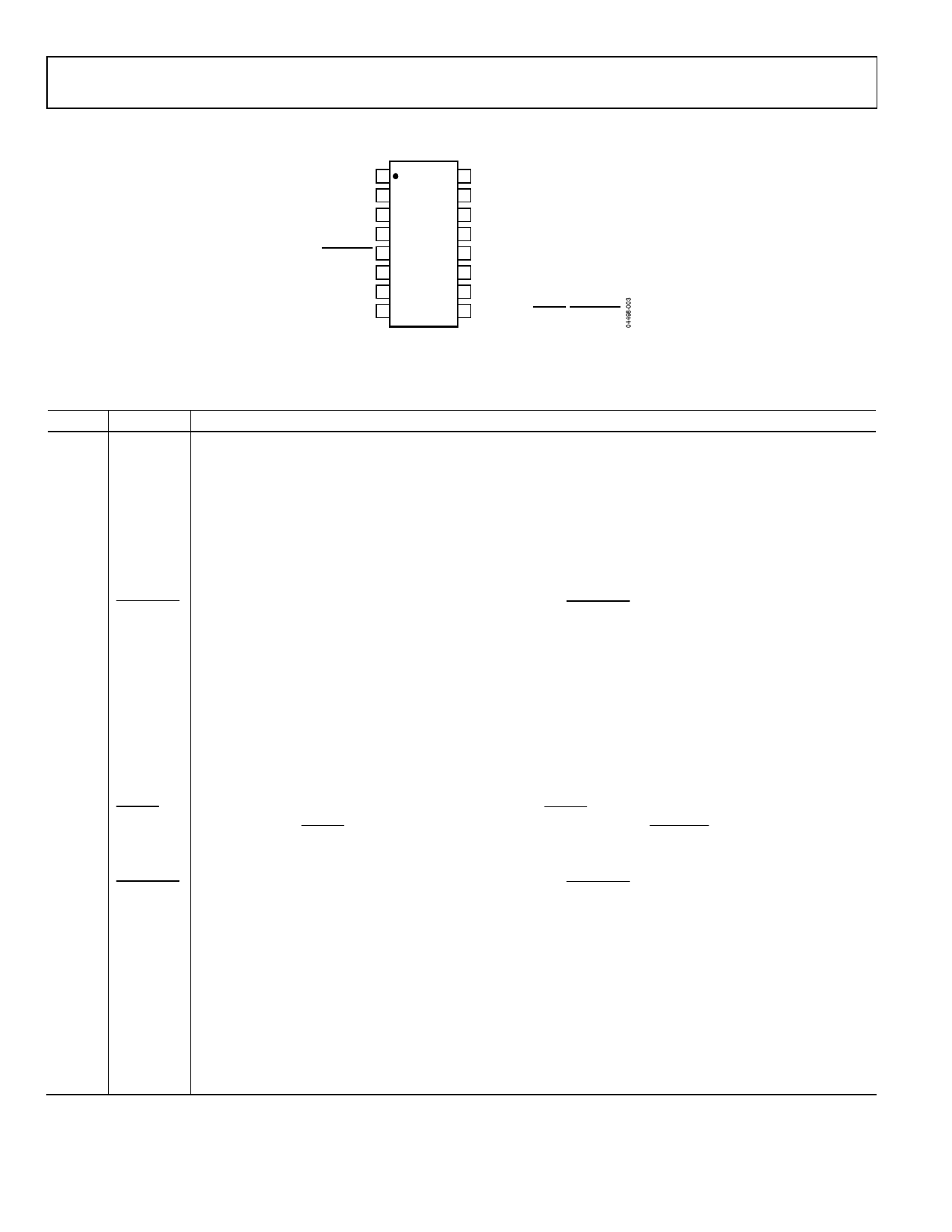
PIN CONFIGURATION AND FUNCTION DESCRIPTIONS
SCL 1
16 SDA
GND 2
15 PWM1/XTO
VCC 3
TACH3 4
PWM2/SMBALERT 5
ADT7467
TOP VIEW
(Not to Scale)
14 VCCP
13 D1+
12 D1–
TACH1 6
11 D2+
TACH2 7
10 D2–
PWM3 8
9 TACH4/GPIO/THERM/SMBALERT
Figure 3. Pin Configuration
Table 3. Pin Function Descriptions
Pin No. Mnemonic Description
1
SCL
Digital Input (Open Drain). SMBus serial clock input. Requires SMBus pull-up.
2
GND
Ground Pin for the ADT7467.
3
VCC
Power Supply. Can be powered by 3.3 V standby if monitoring in low power states is required. VCC is also monitored
through this pin. The ADT7467 can also be powered from a 5 V supply. Setting Bit 7 of Configuration Register 1
(0x40) rescales the VCC input attenuators to correctly measure a 5 V supply.
4
TACH3
Digital Input (Open Drain). Fan tachometer input to measure speed of Fan 3. Can be reconfigured as an analog
input (AIN3) to measure the speed of 2-wire fans (low frequency mode only).
5
PWM2
Digital Output (Open Drain). Requires 10 kΩ typical pull-up. Pulse width modulated output to control the speed of
Fan 2. Can be configured as a high or low frequency drive.
SMBALERT Digital Output (Open Drain). This pin can be reconfigured as an SMBALERT interrupt output to signal out-of-limit
conditions.
6
TACH1
Digital Input (Open Drain). Fan tachometer input to measure speed of Fan 1. Can be reconfigured as an analog
input (AIN1) to measure the speed of 2-wire fans (low frequency mode only).
7
TACH2
Digital Input (Open Drain). Fan tachometer input to measure speed of Fan 2. Can be reconfigured as an analog
input (AIN2) to measure the speed of 2-wire fans (low frequency mode only).
8
PWM3
Digital I/O (Open Drain). Pulse width modulated output to control the speed of Fan 3 and Fan 4. Requires 10 kΩ
typical pull-up. Can be configured as a high or low frequency drive.
9
TACH4
Digital Input (Open Drain). Fan tachometer input to measure speed of Fan 4. Can be reconfigured as an analog
input (AIN4) to measure the speed of 2-wire fans (low frequency mode only).
GPIO
General-Purpose Open-Drain Digital I/O.
THERM
Alternatively, the pin can be reconfigured as a bidirectional THERM pin, which can be used to time and monitor
assertions on the THERM input. For example, the pin can be connected to the PROCHOT output of an Intel®
Pentium® 4 processor or to the output of a trip point temperature sensor. This pin can be used as an output to
signal overtemperature conditions.
SMBALERT Digital Output (Open Drain). This pin can be reconfigured as an SMBALERT interrupt output to signal out-of-limit
conditions.
10
D2−
Cathode Connection to Second Thermal Diode.
11
D2+
Anode Connection to Second Thermal Diode.
12
D1−
Cathode Connection to First Thermal Diode.
13
D1+
Anode Connection to First Thermal Diode.
14
VCCP
Analog Input. Monitors processor core voltage (0 V to 3 V).
15
PWM1
Digital Output (Open Drain). Pulse width modulated output to control the speed of Fan 1. Requires 10 kΩ typical
pull-up.
XTO
Also functions as the output from the XNOR tree in XNOR test mode.
16
SDA
Digital I/O (Open Drain). SMBus bidirectional serial data. Requires 10 kΩ typical pull-up.
Rev. 3 | Page 6 of 77 | www.onsemi.com
Share Link: 