HV9606X データシートの表示(PDF) - Supertex Inc
部品番号
コンポーネント説明
メーカー
HV9606X Datasheet PDF : 9 Pages
| |||
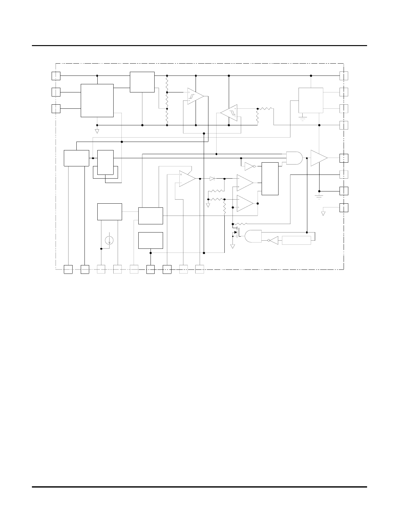
Functional Block Diagram
Vin
STOP
START
Regulator Start-Up
Enable Regulator
Programable
Start/Stop
Circuit
Oscillator
Enable
Vdd
UVLO
C
VX2
UVLO
C
HV9606
Vdd
CA
Voltage
Doubler
CB
VX2
Oscillator
CLK Q
_
D ___ Q
CLR
Soft
Start
Supervisor Enable
Circuit
Soft
Start
Circuit
SQ
A
C
R
R
R
R
C
Current
Limit
Vdd
Bandgap
Reference
Generator
85 nS Delay
GATE
CS
PGND
SGND
RT SYNC STATUS SENSE SS VREF NI
FB COMP
Functional Description
The HV9606 is composed of several functional blocks. The
operation of each of these blocks is described in the following
sections.
Programmable Start/Stop Control Circuit
(Programmable Under Voltage Lockout and Hysteresis)
The START/STOP control circuit is a novel version of a
programmable under voltage lockout with programmable
hysteresis circuit. It is novel, because it requires zero power (other
than the current in the resistor divider) and keeps the startup
regulator shut down until the START threshold voltage is
exceeded, allowing the HV9606 to achieve its low input leakage
current of <6µA.
One can think of the circuit as a transparent latch, such that its
output is high when the START pin is above its threshold voltage
and is latched when the STOP pin is at a voltage greater than the
START pin voltage. It is unlatched when the STOP pin voltage
falls below its threshold voltage and the START pin is below its
threshold voltage.
These operating conditions are met by using a voltage divider
consisting of three resistors (see typical application circuit). The
voltage drop on the resistor connected to ground controls the
START voltage and the additional voltage drop on the middle
resistor sets the hysteresis and controls the STOP voltage. Setting
the value of the middle resistor to zero results in zero hysteresis.
Provided the START and STOP pin input currents are negligible in
comparison to the chosen resistor divider current, the resistor
values may be calculated using the following equations:
R3 = (VSTART / VIN-Start) x (VIN-Stop / IResistor)
R2 = [(VSTOP / VIN-Stop) x (VIN-Stop / IResistor)] – R3
R1 = (VIN-Operating / IResistor) - R2 - R3
Where:
VSTART is the START pin threshold voltage (nominal 7V)
VSTOP is the STOP pin threshold voltage (nominal 7V)
VIN-Start is the input voltage at which starting is desired
VIN-Stop is the input voltage at which shutdown is desired
IResistor is the resistor divider current (>1µA)
5
4/15/2002-R.L2
Supertex, Inc. 1235 Bordeaux Drive, Sunnyvale, CA 94089 TEL: (408) 744-0100 FAX: (408) 222-4895 www.supertex.com
Share Link: 