M29F002 データシートの表示(PDF) - Advanced Micro Devices
部品番号
コンポーネント説明
メーカー
M29F002 Datasheet PDF : 37 Pages
| |||
PRELIMINARY
Sector
SA0
SA1
SA2
SA3
SA4
SA5
SA6
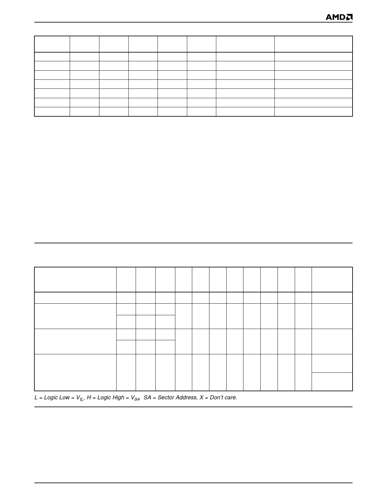
Table 3. Am29F002/Am29F002N Bottom Boot Block Sector Address Table
A17
A16
A15
A14
A13
Sector Size
(Kbytes)
Address Range
(in hexadecimal)
0
0
0
0
X
16
00000h–03FFFh
0
0
0
1
0
8
04000h–05FFFh
0
0
0
1
1
8
06000h–07FFFh
0
0
1
X
X
32
08000h–0FFFFh
0
1
X
X
X
64
10000h–1FFFFh
1
0
X
X
X
64
20000h–2FFFFh
1
1
X
X
X
64
30000h–3FFFFh
Autoselect Mode
The autoselect mode provides manufacturer and de-
vice identification, and sector protection verification,
through identifier codes output on DQ7–DQ0. This
mode is primarily intended for programming equipment
to automatically match a device to be programmed with
its corresponding programming algorithm. However,
the autoselect codes can also be accessed in-system
through the command register.
When using programming equipment, the autoselect
mode requires VID (11.5 V to 12.5 V) on address pin
A9. Address pins A6, A1, and A0 must be as shown in
Autoselect Codes (High Voltage Method) table. In addi-
tion, when verifying sector protection, the sector ad-
dress must appear on the appropriate highest order
address bits. Refer to the corresponding Sector Ad-
dress Tables. The Command Definitions table shows
the remaining address bits that are don’t care. When all
necessary bits have been set as required, the program-
ming equipment may then read the corresponding
identifier code on DQ7–DQ0.
To access the autoselect codes in-system, the host
system can issue the autoselect command via the
command register, as shown in the Command Defini-
tions table. This method does not require VID. See
“Command Definitions” for details on using the autose-
lect mode.
Table 4. Am29F002/Am29F002N Autoselect Codes (High Voltage Method)
Description
A17 A12
A8
A5
to to
to
to
CE# OE# WE# A13 A10 A9 A7 A6 A2 A1 A0
DQ7
to
DQ0
Manufacturer ID: AMD
Device ID:
Am29F002/Am29F002N
(Top Boot Block)
L
L
H
X
X VID X
L
X
L
L
01h
L
L
H
X
X VID X
L
X
L
H
B0h
L
L
H
Device ID:
Am29F002/Am29F002N
(Bottom Boot Block)
L
L
H
X
X VID X
L
X
L
H
34h
L
L
H
01h
(protected)
Sector Protection Verification
L
L
H SA X VID X
L
X
H
L
00h
(unprotected)
L = Logic Low = VIL, H = Logic High = VIH, SA = Sector Address, X = Don’t care.
Sector Protection/Unprotection
The hardware sector protection feature disables both
program and erase operations in any sector. The
hardware sector unprotection feature re-enables both
program and erase operations in previously pro-
tected sectors.
Sector protection/unprotection must be implemented
using programming equipment. The procedure re-
quires a high voltage (VID) on address pin A9 and the
control pins. Details on this method are provided in the
supplements, publication numbers 20819 and 21183.
Am29F002/Am29F002N
9
Share Link: 