AN6263 データシートの表示(PDF) - Panasonic Corporation
部品番号
コンポーネント説明
メーカー
AN6263 Datasheet PDF : 5 Pages
| |||
AN6262N, AN6263N
s Operational Description
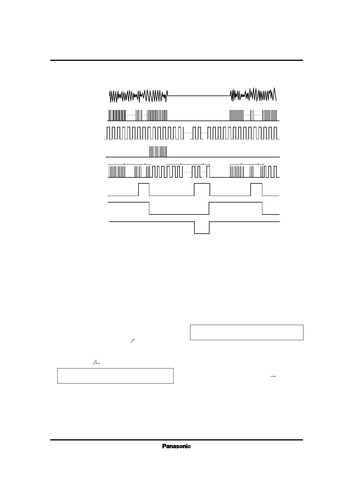
(1) Between the program timing chart (PLAY Mode)
Music
Sound Signal
ICs for Cassette, Cassette Deck
Pause between the music
Music
Sound Signal
Pulse
Oscillation
Signal Pulse
Reset
Counter Input
3712 Pulse 256 Pulse
3712 Pulse 256 Pulse
3712 Pulse 256 Pulse
FF12
FF13
Output
(Output polarity is inverted in case of AN6263N)
(2) Explanation of PLAY mode (Referred to block diagram)
1) When supply voltage is turned ON and Pin3 is set to “H” 9) Sound pulse signal, oscillation from oscillator and output of
(between the program detection ON), FF1-FF12 are reset and
FF12 are connected to reset pin of the counter, input of the
FF13 is set, Switch SW1 is all connected to a.
2) Mode is set (Pin7 “L”, Pin8 “H”).
counter and output circuit, respectively.
10) Counter will count oscillation pulse signal and is reset by
3) SW2 is connected to a.
the “H” of sound pulse signal (Program is there).
4 ) Sound signal input to P i n 1 becomes pulse after wave 11) When sound pulse signal is stayed at “L” (program ends),
shaped.
reset is released. Counter begins to count oscillation pulse
5) This sound pulse signal is input to the counter via
signal and FF12 is inverted to “H” by 3712 pulses.
SW1-2.
6) Sound pulse signal is input to the counter by 3712
pulses, FF12 is inverted to “H” (L H). But no output is
obtained as the SW1– 4 is connected to a.
7) Furthermore sound pulse signal is input by 256, FF12 in
Between the program is detected by counting
oscillation pulse signal by 3712 pulses.
When static capacitance of the external capacitor at Pin9 is
set to 0.1µF, between the program is detected when no
inverted to “L” ( L).
When sound pulse signal is input by 3712+256
pulses, program is recognized.
8) When FF12 is inverted from “H” to “L”, FF13 is inverted.
signal time is more than 3 seconds.
12) Oscillation pulse signal is input furthermore by
256 pulses, FF12 is inverted (“H” “L”), FF13 is
also inverted and SW1 is all connected to a.
13) Returns to 5) mode. Input pulse signal is counted by more
When FF13 is inverted, SW1 is all connected to b.
than 3712 + 256 pulses, program is recognized.
Share Link: 