AN7198Z データシートの表示(PDF) - Panasonic Corporation
部品番号
コンポーネント説明
メーカー
AN7198Z Datasheet PDF : 20 Pages
| |||
ICs for Audio Common Use
s Technical Information (continued)
2. Main Characteristics (continued)
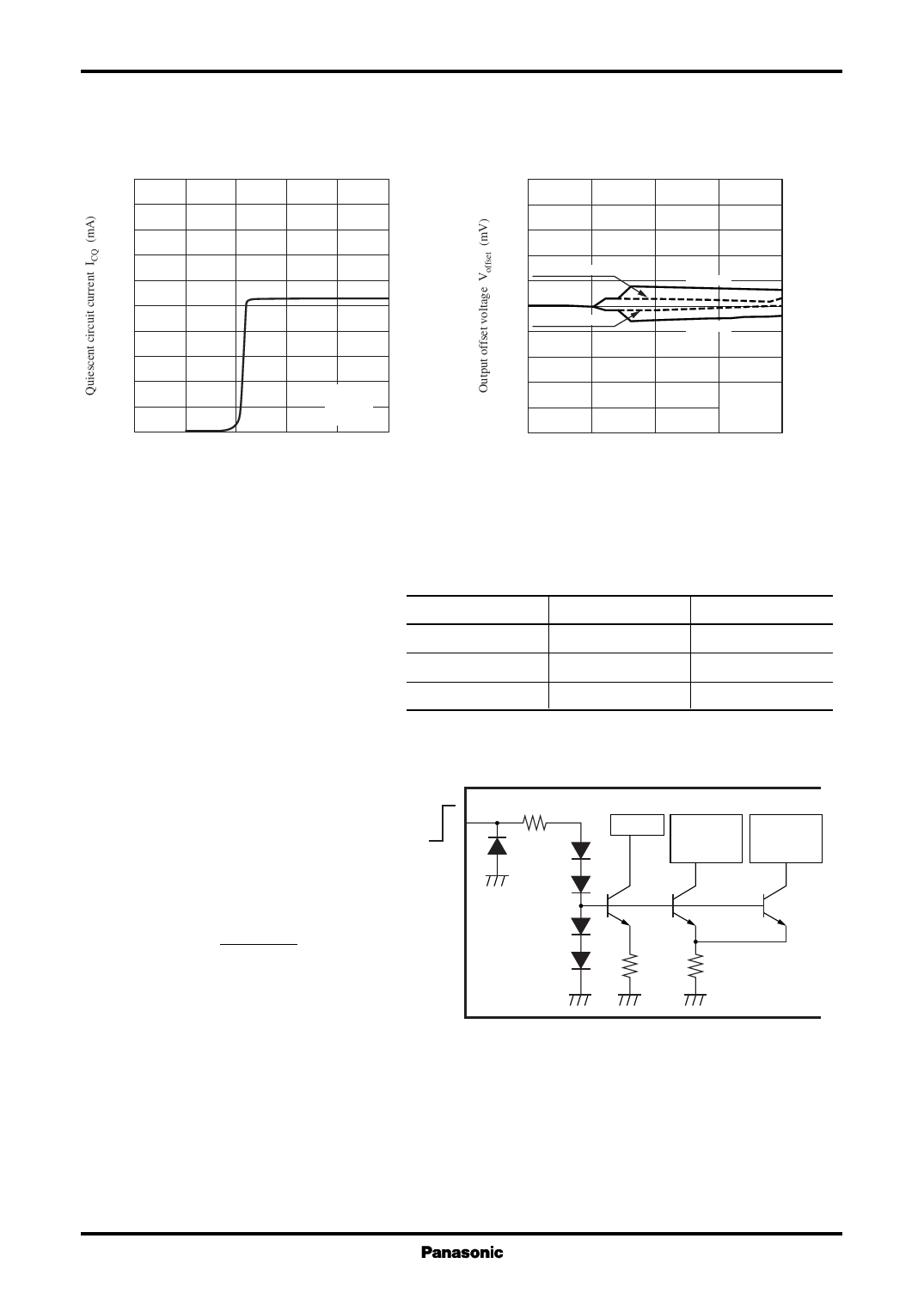
ICQ VSTB
200
180
160
140
120
100
80
60
40
VCC = 13.2 V
20
RL = 4 Ω
Rg = 10 kΩ
0
0
1
2
3
4
5
Standby voltage VSTB (V)
AN7198Z
Voffset VCC
250
200
150
100
channel 1 mute on
50
channel 1
0
channel 2 mute on
−50
channel 2
−100
−150
−200
−250
0
RL = 4 Ω
Rg = 10 kΩ
5
10
15
20
Supply voltage VCC (V)
3. Application note
1) Standby function
(1) The power can be turned on or off
by making pin 5 (standby terminal)
high or low.
Terminal state
Open
Terminal voltage
0V
Power
Standby state
(2) The standby terminal has threshold
voltage of approx. 2.1 V, however, it
has temperature dependency of approx.
−6 mV/°C. The recommended range
of use is shown in Table 1.
Low
High
0 V to 1.0 V
Higher than 3 V
Table 1
Standby state
Operating state
(3) The internal circuit of standby termial
is as shown in Figure 1. When the 5 V
standby terminal is high, the VSTB
current approximately expressed
0V
by the following equation will
flow into the circuit.
5
10 kΩ
Sub
RF
Protection
circuit
Constant
current
source
ISTB=
VSTB−2.7 V
10 kΩ
[mA]
2 kΩ 4 kΩ
Figure 1
(4) A power supply with no ripple component should be used for the control voltage of standby terminal.
11
Share Link: 