AN7198Z データシートの表示(PDF) - Panasonic Corporation
部品番号
コンポーネント説明
メーカー
AN7198Z Datasheet PDF : 20 Pages
| |||
ICs for Audio Common Use
AN7198Z
s Technical Information (continued)
3. Application note (continued)
8) Mute function (continued)
(4) Attack time and recovery time can be changed by the external CR of pin 7. For recommended circuits (Figure 7
22 kΩ , 1 µF), the above mentioned times are as follows:
Attack time: Approx. 30 ms
Recovery time: Approx. 40 ms
However, the control voltage of VMUTE is assumed to be 5 V. When it is not directly controlled by
microcomputer (5 V), (such as 13.2 V separate power supply), it is necessary to change CR values because
the above times change.
(5) When the attack time and recovery time are set at 20 ms or less, pay attention to the IC with larger output
offset because it may release the shock noise.
9) Voltage gain
The voltage gain is fixed at 34 dB for the AN7198Z, and 40 dB for the AN7199Z. It is not possible to change those
values by the addition of an external resistance.
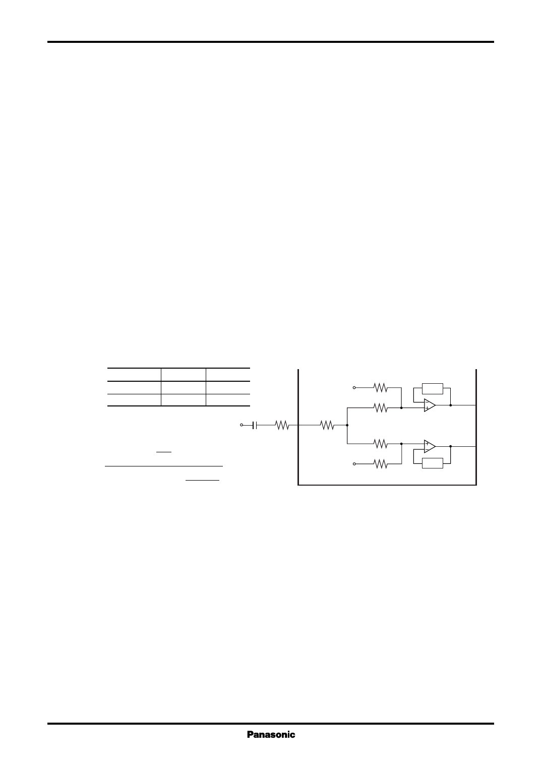
10) Beep sound input function
(1) The application circuit example when using the beep sound input is shown in Figure 8. Connect the beep signals
from the microcomputer to pin 10 via the capacitor C1 for DC cut and the resistor R1 for voltage gain adjustment.
(2) The voltage gain of beep sound terminal is approx. −6.2 dB.
The setting value of Figure 8 becomes approx. −19.7 dB (f = 1 kHz).
(3) The beep sound is outputted to the output terminals, pin 2 and pin 15.
AN7198Z
AN7199Z
Rnf
600 Ω
300 Ω
GVA
28 dB
34 dB
VREF = 6.3 V
C1 47 kΩ
Beep input
0.022 µF R1
Rnf
2
GVBEEP = 1/jωC1+R1+7.8 Κ+ 15 k+Rnf × GVA
2
Figure 8
10 7.8 kΩ
VREF = 6.3 V
Rnf
15 kΩ
15 kΩ
Rnf
GVA
2
15
GVA
15
Share Link: 