AN723 データシートの表示(PDF) - Vishay Semiconductors
部品番号
コンポーネント説明
メーカー
AN723 Datasheet PDF : 8 Pages
| |||
AN723
Vishay Siliconix
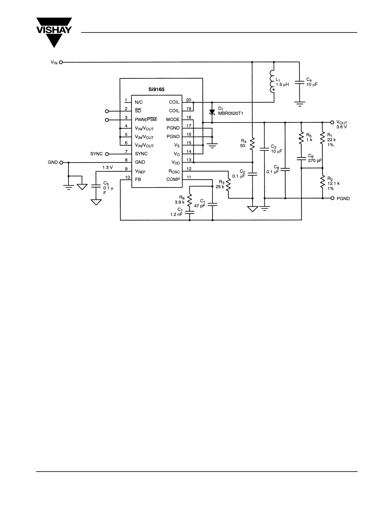
FIGURE 3. Typical Application Circuit—Boost
DESIGN GUIDELINES
Following are some design guidelines for buck and boost
converters. The Si9165 combines a high level of integration
while allowing the designer a considerable measure of
flexibility. Key components required for a complete converter
design are an inductor, input/output capacitors, and a
compensation network.
Inductor Selection
An inductor is the energy storage component in a converter.
Choosing an inductor means specifying its size, structure,
material, inductance, saturation level, dc-resistance (DCR),
and core loss. Fortunately, there are many inductor vendors
that offer wide selections with ample specifications and test
data, such as Vishay-Dale, Coilcraft, Coiltronics, and Sumida.
The following are some key parameters that users should
focus on.
In PWM mode, inductance has a direct impact on the ripple
current. The peak-to-peak inductor ripple current can be
calculated as
For Buck, Ip – p
=
-V----O----U---T---(---V----I--N----–-----V----O----U----T---)
VINLF
(1)
For Boost, Ip – p
=
-V----I-N-----⋅---(--V-----O---U----T----–-----V----I--N---)-
VOUTLF
(2)
where f = switching frequency.
Higher inductance means lower ripple current, lower rms
current, lower voltage ripple on both input and output, and
higher efficiency, unless the resistive loss of the inductor
dominates the overall conduction loss. However, higher
inductance also means a bigger inductor size and a slower
response to transients. In PSM mode, inductance affects
inductor peak current, and consequently impacts the load
capability and switching frequency. For fixed line and load
conditions, higher inductance results in a lower peak current
for each pulse, a lower load capability, and a higher switching
frequency.
The saturation level is another important parameter in
choosing inductors. Note that the saturation levels specified in
datasheets are maximum currents. For a dc-to-dc converter
operating in PWM mode, it is the maximum peak inductor
current that is relevant, and which can be calculated using
these equations:
For Buck, Ipk
=
IOUT
+
-I-p----–---p-
2
(3)
For Boost, Ipk
=
V-----O----U---T---I--O----U----T- + -I-p----–---p-
ηVIN
2
(4)
where η = converter efficiency.
This peak current varies with inductance tolerance and other
errors, and the rated saturation level varies over temperature.
So a sufficient design margin is required when choosing
current ratings.
A high-frequency core material, such as ferrite, should be
chosen, since at 2 MHz, the core loss could lead to serious
efficiency penalties. The DCR should be kept as low as
possible to reduce conduction losses.
FaxBack 408-970-5600, request 70823
www.siliconix.com
3
Share Link: 