AN727 データシートの表示(PDF) - Vishay Semiconductors
部品番号
コンポーネント説明
メーカー
AN727 Datasheet PDF : 8 Pages
| |||
AN727
Vishay Siliconix
In the Si9167, the error amplifier output is compared with the
0.5-V peak-to-peak sawtooth waveform elevated by a 0.5-V
offset (Figure 3). The offset provides sufficient noise immunity,
even at 2-MHz switching frequencies and 1V/nSec MOSFET
switching. The error amplifier has an open loop gain of 60 dB
with a 2-MHz unity gain bandwidth. This feature helps to
simplify compensation and further increase the closed loop
bandwidth. The only external component required to set the
oscillator frequency is a resistor at Rosc (pin12). The oscillator
generates a "20% tolerance frequency with a "1% resistor.
High Frequency Operation
Low power dc-to-dc regulator designers must consider both
the on-resistance of the switches and the gate charge required
to turn them on and off. Conventional MOSFETs need more
gate charge per ampere of current rating, while Vishay
Siliconix’s extremely low gate charge, PWM optimized
MOSFET technology offers optimum performance even
above 1-MHz switching frequencies. The Si9167 has 180-mW
internal drivers and requires a very low gate charge drive,
translating into lower switching losses at higher frequencies.
Moreover, lower gate charge helps increase the switching
speed for a given drive power. This further improves efficiency
by reducing crossover losses. For this reason, the Si9167 can
achieve up to 93% efficiency even when operating at 1 MHz.
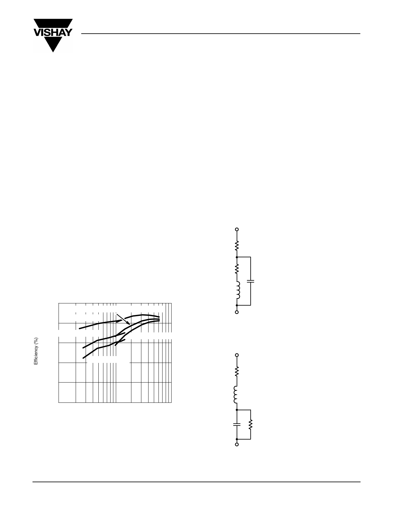
Efficiency curves for a 3.6-V buck regulator at various input
voltage levels are provided in Figure 4.
Efficiency, VO = 3.6 V
100
PWM–VIN = 7.2 V
PWM–VIN = 5 V
PSM–VIN = 5 V
90
PSM–VIN = 7.2 V
80
PWM–VIN = 8.4 V
70
PSM–VIN = 8.4 V
60
50
10
100
Load Current (mA)
FIGURE 4. Efficiency vs. Output Load
1000
hysteresis losses in an inductor, as well as ESR losses in
capacitors, are the limiting factors in going to higher operating
frequencies. Moreover, the effective impedance of capacitors
and inductors at higher operating frequencies are dominated
by ESL, ESR, and interlayer capacitance, which causes
inductors to behave more like capacitors and capacitors to
behave more like inductors.
The low-profile, high-current IHLP inductor series from
Vishay Dale offers excellent high-frequency performance, as
do very low-ESR, high-capacity multilayer ceramic capacitors,
such that output ripple is inversely proportional to the switching
frequency and not determined by the ESR. The X5R series
from Murata and the Y5U series from Tokin are recommended
dielectrics.
Practical Inductor
Rdc
Rdc = dc Resistance of Copper
Rac = Skin Effect Related ac resistance
Cp = Interlayer Capacitance
Rac
L Ideal Inductance
Cp
L
Practical Capacitor
RESR
RESL
RESR = Equivalent Series Resistance
Rp = Insulation Resistance
C = Interlayer Capacitance
RESL Equivalent Series Inductance
C
Rp
Passive Components
Within limits, high switching frequencies reduce the size of
passive components. Frequency-dependent skin effect and
Document Number: 70959
07-Jul-99
FIGURE 5.
www.vishay.com S FaxBack 408-970-5600
3
Share Link: 