AN701 データシートの表示(PDF) - Vishay Semiconductors
部品番号
コンポーネント説明
メーカー
AN701
Vishay Semiconductors

AN701 Datasheet PDF : 19 Pages
| |||
AN701
Vishay Siliconix
11
12
10
11
9
10
8
9
7
25
35
45
55
65
75
Temperature (_C)
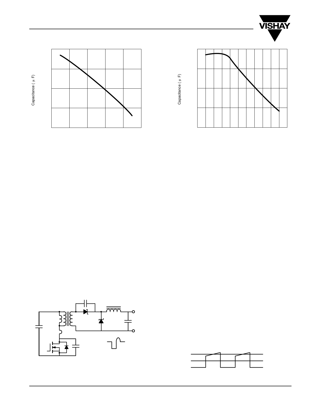
Figure 17. Marcon 10 mF 25 V, Capacitance Versus
Temperature
8
0 1 2 3 4 5 6 7 8 9 10 11
Voltage (V)
Figure 18. Marcon 10 mF 25 V, Capacitance Change
with Voltage
DESIGN EXAMPLE: A 15ĆW, 500ĆKHZ, 48ĆV/5ĆV DCĆTOĆDC CONVERTER
Resonant Reset Forward Converter
Most forward converters are designed using a clamp circuit.
While at low frequencies this technique may be acceptable, at
high frequencies it becomes unnecessary: the parasitic
elements of the circuit will reset the transformer flux
automatically, provided a few precautions are taken.
It has been shown that [1] the resonant reset concept is
dominated by the parasitic capacitance of the MOSFET and
the magnetizing inductance of the transformer. Yet the
capacitance of the output diode should also be considered.
The correct equivalent circuit of the converter the
approximates to Figure 19.
at a frequency determined by the parasitic elements. The reset
period needs to be short enough to allow full reset of the core,
before the next switching interval occurs. This will be governed
by the selection of the MOSFET and the Schottky diode.
Component Selection
The following information is supplied in order to help designer
select correct components for use with the Si9114A.
Vishay Siliconix does not necessarily recommend or approve
these components for specific applications. Designers should
contact manufacturers directly to obtain correct and current
data sheets.
During the off time, D2 is conducting and CD1 appears
connected across the primary of the transformer, in parallel
with LMAG. The leakage inductance has a small and
insignificant effect on the waveform—as the primary current
has ceased flowing—and the only remaining current is the
current that is charging COUTĄ.
CD1
Lout
N=1
Lmag
Cin
CAP
D1
D2
Cout
Q1
Cout
Vds
Figure 19 Resonant Reset Forward Converter
Capacitor Selection
As stated previously, ceramic capacitors are a good choice
when operating at high frequency, due to the extremely low
ESR, and high reliability, and long operating lifetimes.
In the design example, the required size of capacitors was
defined as follows:
Input capacitor:
A 15-W output converter with 85% efficiency will require
15/0@85 = 17.65 W of input power. Assuming that operation
at nominal conditions is 48 V, with duty cycle of δ=0.376
(measured), the switching current will be governed by the
size of the output inductor (Figure 20).
lA
lDC
In effect, the magnetizing inductance of the transformer forms
a parallel tuned circuit across the transformer and resonates
Figure 20
www.vishay.com
10
Document Number: 70575
16-Jan-01
Share Link: