AN709 „Éá„Éľ„āŅ„ā∑„Éľ„Éą„ĀģŤ°®Á§ļÔľąPDFÔľČ - Vishay Semiconductors
ťÉ®ŚďĀÁē™ŚŹ∑
„ā≥„É≥„ÉĚ„Éľ„Éć„É≥„ÉąŤ™¨śėé
„É°„Éľ„āę„Éľ
AN709
Vishay Semiconductors

AN709 Datasheet PDF : 7 Pages
| |||
AN709
Vishay Siliconix
INPUT VOLTAGE REQUIREMENTS
The Si9976DY operates from a single supply voltage of 20 to
40 V dc. This voltage feeds both the bootstrap and the
low-voltage regulators. The bootstrap voltage regulator
charges the bootstrap capacitor, while the low-voltage
regulator drops the input voltage to a nominal VDD of 16 V for
the low-side logic and the output drive for the low-side
MOSFET.
If the FAULT output is used, a separate voltage (4.5 to 16 V), must
be applied to the VCC pin. This guarantees compatibility with the
logic levels in the motor controller.
OUTPUT DRIVE DETAILS
A unique feature of the Si9976DY is the integral high-side drive
circuitry. This includes logic-signal level shifting, a bootstrap
power supply, a charge pump, an undervoltage lockout, and a
40-mA output driver.
A bootstrap supply and a charge pump comprise the high-side
power supply, and utilize the benefits of each technique. By
itself, bootstrap supply provides sufficient charge for MOSFET
turn-on. However, it has two drawbacks when used alone.
First, a bootstrap capacitor must be recharged after every
MOSFET turn-on. Second, a bootstrap supply cannot sustain
a MOSFET in the on state indefinitely because the gate
leakage current continues to deplete the charge on the
bootstrap capacitor. A charge pump meanwhile, can provide
a continuous source of charge, but in fully integrated form it
cannot provide sufficient charge for MOSFET turn-on at typical
modulation frequencies. Combining the two techniques solves
these problems. The bootstrap supply provides the turn-on
charge while the charge pump provides the leakage current to
allow static operation.
Because a bootstrap supply is used, the bootstrap capacitor
must get charged immediately after power on and then be
recharged after every high-side turn on. Likewise, the low-side
MOSFET must be turned on to complete the charging circuit
for the bootstrap capacitor. Some drive schemes toggle
between the top and bottom MOSFETs, which accomplishes
the required charge and recharge of the bootstrap capacitor
automatically. It is important to understand that the charge
pump operates only when the high-side is turned on.
The bootstrap capacitor provides the charge that turns on the
high-side MOSFET. This capacitor should be sized such that it will
hold 10 times the charge required to turn on a MOSFET fully (i.e.,
VGS = 10 V). A typical capacitor value can be calculated by using
the equation CBOOT = 10 x (Qg/VGS). The value of Qg is taken
from the gate charge curve of the MOSFET being driven at VGS
=10 V. Using this method of capacitor selection, the bootstrap
voltage will drop approximately 1 V when the MOSFET is
turned on. A 0.018-mF capacitor works well for the Si9945DY,
which requires a 15-nC charge to turn on with VGS = 10 V.
A certain minimum recharge time is required for the bootstrap
capacitor after each high-side turn-on. The recharge time is a
function of the amount of charge which has been used to turn
on the high-side MOSFET, the size of the bootstrap capacitor,
and the drain current of the bootstrap transistor in the
Si9976DY. In the case of the Si9976DY, the recharge time
decreases as V+ increases. Part of this decrease is due to the
contribution of the charge pump to the recharging of the
bootstrap capacitor. As V+ increases, the charge pump
contribution increases. In some cases, the charge pump
becomes the only source of charge required to recharge the
bootstrap capacitor.
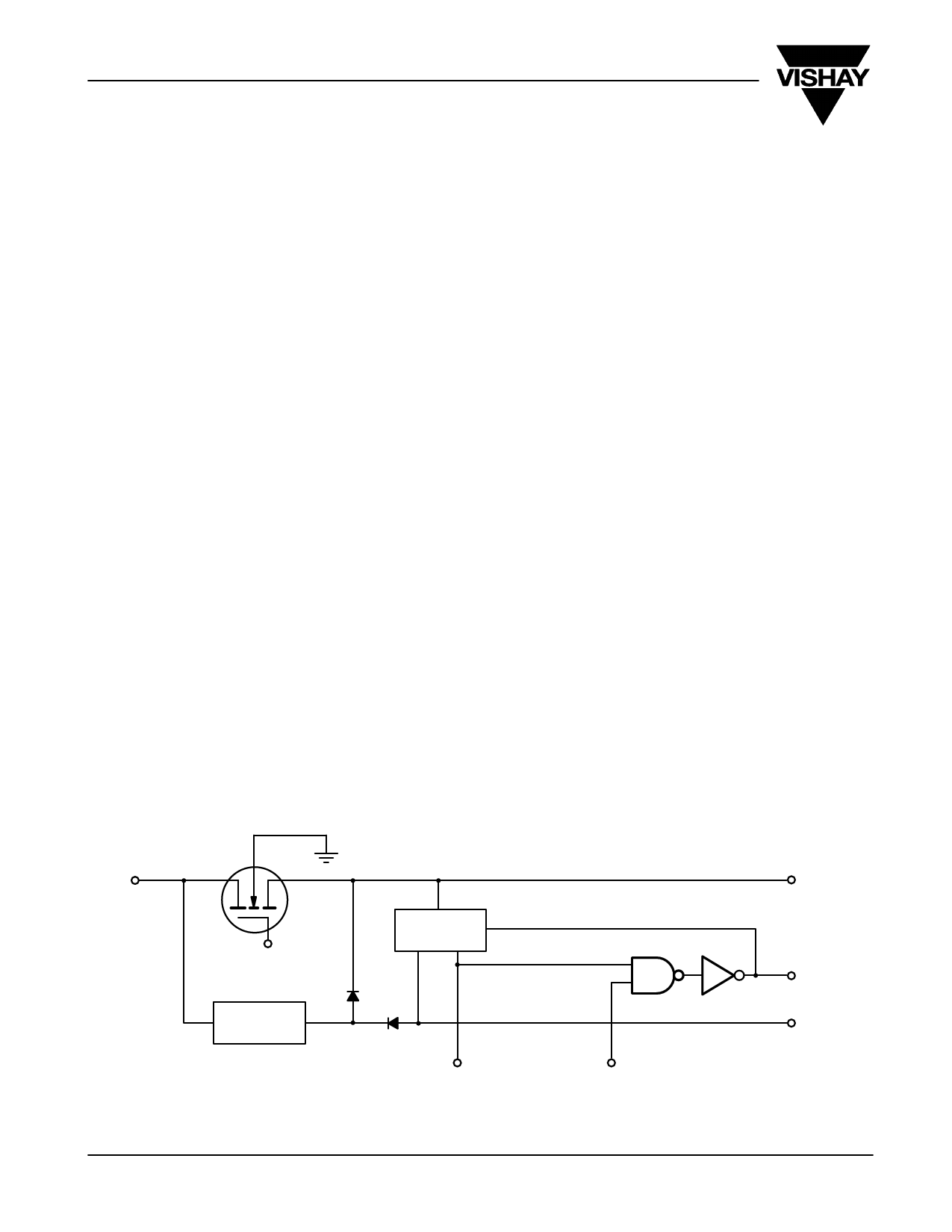
Bootstrap
Regulator
V+
VDD
Charge
Pump
www.vishay.com S FaxBack 408-970-5600
2
Under Voltage
Lockout 1
To High-Side Logic
Figure 2. High-Side Drive
CAP
G1
S1
From High-Side Logic
Document Number: 70582
15-Jun-00
Share Link: