AN709 „Éá„Éľ„āŅ„ā∑„Éľ„Éą„ĀģŤ°®Á§ļÔľąPDFÔľČ - Vishay Semiconductors
ťÉ®ŚďĀÁē™ŚŹ∑
„ā≥„É≥„ÉĚ„Éľ„Éć„É≥„ÉąŤ™¨śėé
„É°„Éľ„āę„Éľ
AN709
Vishay Semiconductors

AN709 Datasheet PDF : 7 Pages
| |||
AN709
Vishay Siliconix
Si9976
Si9976
Dual
Dual
DIR
IN
LITTLE
LITTLE
IN
FOOT
FOOT
MOSFET
MOSFET
EN
EN
PWM
DIR
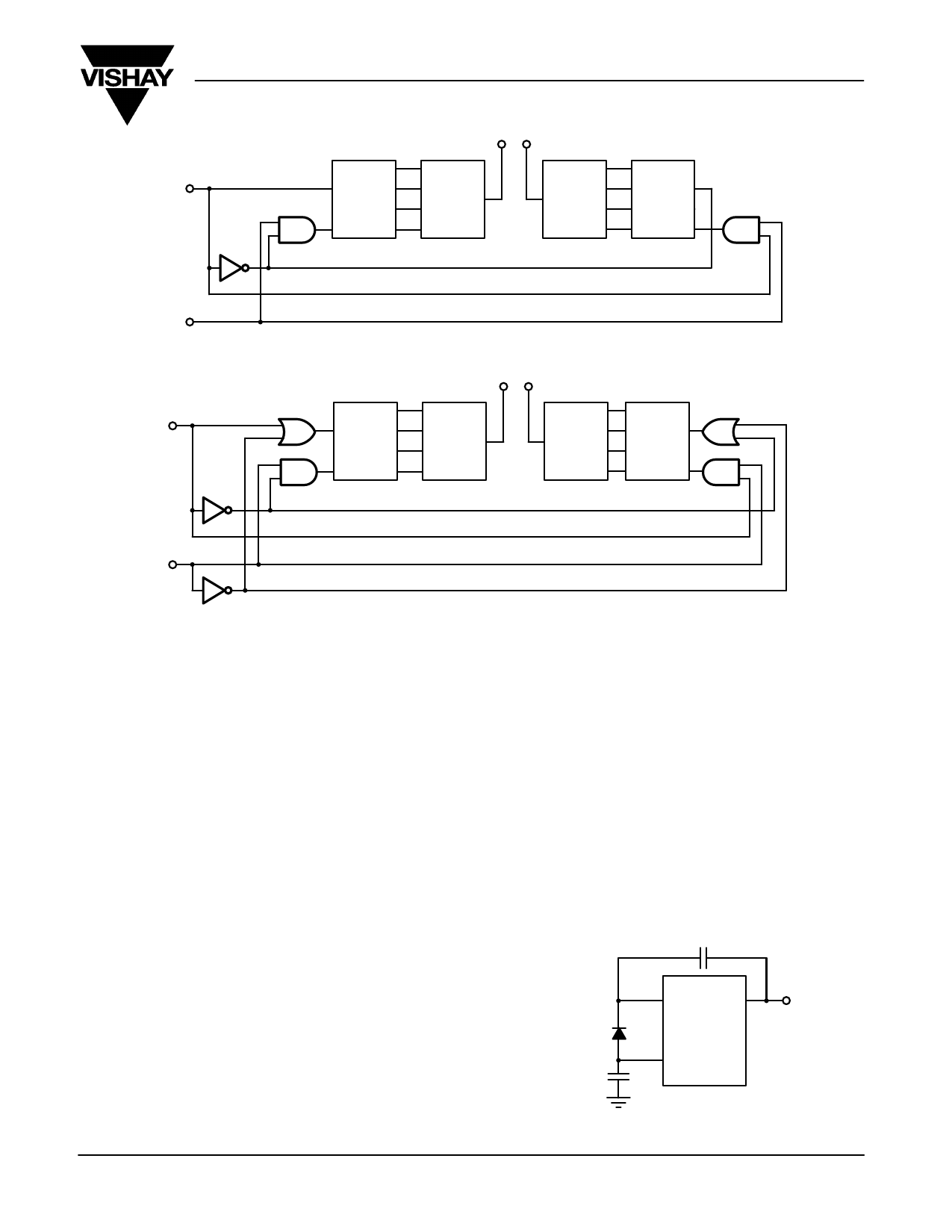
Figure 7a. Sign-Magnitude Control
Si9976
IN
EN
Dual
LITTLE
FOOT
MOSFET
Dual
LITTLE
FOOT
MOSFET
Si9976
IN
EN
PWM
Figure 7b. Sign-Magnitude Control for Low-Side MOSFET PWM
There are a couple of things to be aware of in this mode of
operation. Application of the PWM signal to the EN input when
the IN input is held low will create an erroneous Fault signal
which is the inverse of the PWM signal. This can be eliminated
by applying the inverse of the PWM signal to the IN input as
shown in Figure 7b. Secondly, care must be taken to ensure
that the bootstrap capacitor has been charged prior to a
high-side turn on. As low-side on-times decrease, this
becomes of greater concern. Minimum low-side on-times must
be observed to ensure that the high-side will turn on.
Remember that this minimum time can be reduced by adding
an external bootstrap diode (see Figure 8). When this is done,
it increases the load on VDD and therefore on the decoupling
capacitor. The value of the VDD decoupling capacitor should
be doubled to prevent an undervoltage condition from
occurring.
CURRENT SENSING
If current sensing is required, a fractional W resistor can be
inserted in between the low-side MOSFET source connection
and ground. External op amps or comparators can then be
used to implement current limit or some other current control.
A Schottky diode must be connected from the half-bridge
output to ground to protect output from negative voltage
spikes. In addition to causing potential damage to the Si9976,
negative spikes can cause an erroneous latching FAULT. The
sensing resistor provides a small amount of isolation of the
MOSFET decoupling capacitors from ground. Make sure that
decoupling capacitors on MOSFETs are connected directly
across the MOSFET pair, high-side drain to low-side source to
maximize their effectiveness at reducing noise (see Figure 7).
CBOOT
BRAKING
Braking is accomplished by turning on both upper or both lower
MOSFETs in the H-bridge so the motor windings are shorted
together. If the upper MOSFETs are used for this function, be
certain that the bootstrap capacitors are charged prior to
turning them on.
IN4148
or
Equivalent
2 x CDD
CAP
S1
Si9976
VDD
Document Number: 70582
15-Jun-00
Figure 6. External Bootstrap Diode
www.vishay.com S FaxBack 408-970-5600
5
Share Link: