AN709 „Éá„Éľ„āŅ„ā∑„Éľ„Éą„ĀģŤ°®Á§ļÔľąPDFÔľČ - Vishay Semiconductors
ťÉ®ŚďĀÁē™ŚŹ∑
„ā≥„É≥„ÉĚ„Éľ„Éć„É≥„ÉąŤ™¨śėé
„É°„Éľ„āę„Éľ
AN709
Vishay Semiconductors

AN709 Datasheet PDF : 7 Pages
| |||
AN709
Vishay Siliconix
A FULLńÜBRIDGE APPLICATION
Figure 8 shows a basic implementation of the Si9976DY and
Si9945DY in a full-bridge configuration. Each half-bridge is
made up of one Si9976DY driver IC, one Si9945DY LITTLE
FOOT dual n-channel MOSFET, a bootstrap capacitor, a filter
capacitor for VDD, and decoupling capacitors for each IC. This
configuration yields a full-bridge circuit with a continuous
current rating of 3 A without heatsinking. Use of the
Si9945DY or the Si4946EY yields current ratings of 3.7 A or
4.5 A, respectively.
Any circuit which generates signals with fast rise and fall times
can generate noise. This noise, if not dealt with, can affect the
operation of the circuit. Proper PC board layout techniques
and device decoupling will take care of these problems. The
signal ground trace from the Si9976DY and the trace from the
low-side MOSFET source should be run separately to the
common ground point. This prevents the noise generated by
fast MOSFET transitions from modulating the signal ground of
the Si9976DY. Similarly, the trace to the V+ input of the
Si9976DY and the trace to the drain of the high-side MOSFET
should be connected separately to the supply bypass
capacitor.
In addition to layout considerations, decoupling capacitors are
required to deal with noise. Adding capacitors across the
power supply lines, V+, VDD, and VCC, provides a low
impedance to ground for switching noise and serves as a local
energy reservoir when there is a demand for surge current.
The VDD capacitor provides the surge current required to turn
on the low-side MOSFET.
In addition to basic decoupling, the capacitors added across
the half-bridge itself minimize the surge current in the power
supply traces, and therefore reduce the generated noise.
Although a single capacitor, typically 0.01 mF, works well to
decouple a single pin, it is advisable to apply several decades
of capacitance across the input power, V+ to GND, to handle
the broad spectrum of noise that can be present. The
high-frequency (lower value) capacitors should be located as
close as possible to the device being decoupled, while the
larger capacitors (> 1 mF) can be located farther away and
bypass only the power supply.
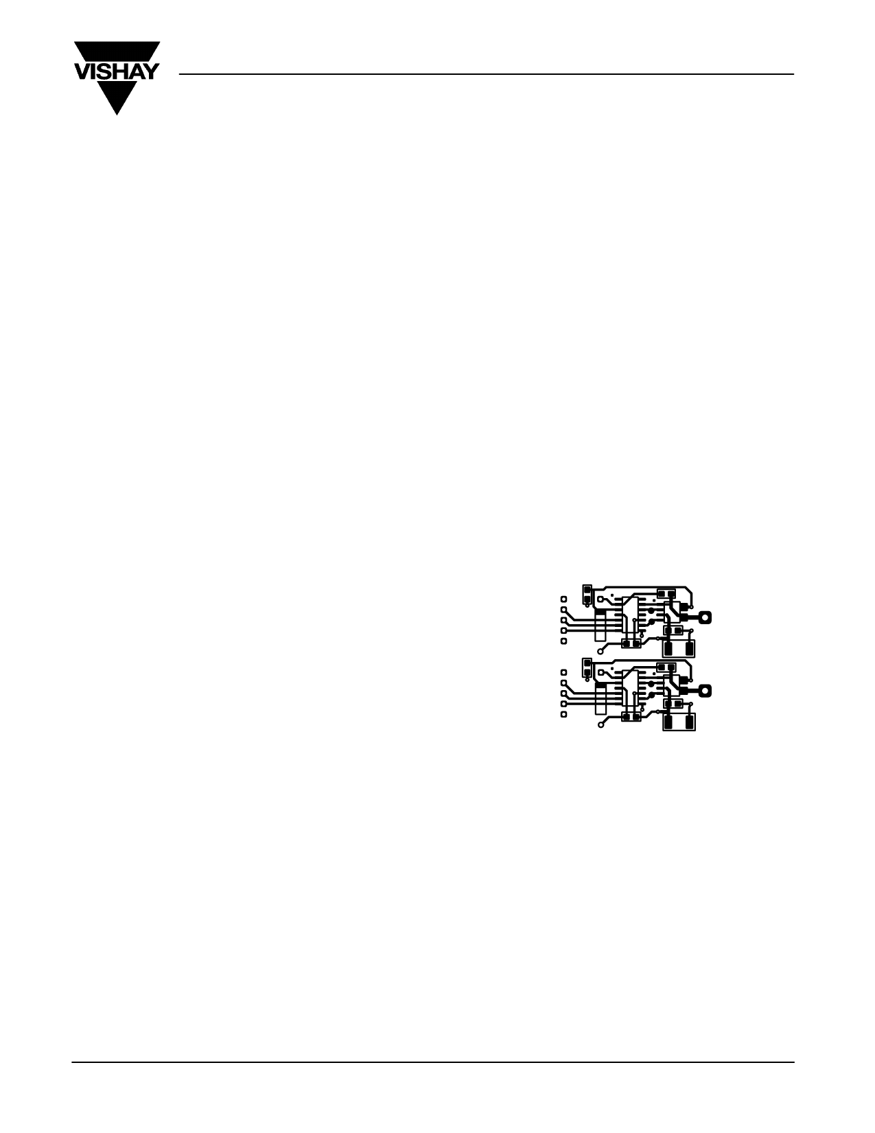
Figure 9 shows a typical layout for a Si9976DY with LITTLE
FOOT dual n-channel MOSFETs. The use of surface-mount
packages allows automated assembly of the entire motor drive
circuit, without the need for a separate heatsink and its
associated material and assembly costs.
SUMMARY
The Si9976DY provides both low- and high-side gate drive,
high-side level shifting, a bootstrap/charge pump high-side
power supply, and protection for undervoltage and short circuit
conditions in a single surface-mount IC. The Si4946EY,
Si9945DY, are Si9945DY are surface-mount MOSFETs for
power switching over a broad current range (2 to 5 A) and
require no heatsinking. The use of surface-mount packages
allows automated assembly of the entire drive system while
minimizing use of PC board space. The Si9976DY, when used
with one of the dual n-channel LITTLE FOOT power
MOSFETs, provides a very flexible approach to power
switching in dc motor drives.
C1
GND
IN
EN
VCC
FAULT
C6
GND
IN
EN
VCC
FAULT
C3
U1
U2
A
C4
D1 C2 C8
U3
C5
U4
B
C9
D2
C10
C7
Figure 9 Typical PC Board Layout (Scale 1:1)
Document Number: 70582
15-Jun-00
www.vishay.com S FaxBack 408-970-5600
7
Share Link: