MAX618 データシートの表示(PDF) - Maxim Integrated
部品番号
コンポーネント説明
メーカー
MAX618 Datasheet PDF : 15 Pages
| |||
MAX618
28V Internal Switch, Step-Up DC-DC Converter
Pin Description
PIN
1, 8, 9,
12, 16
2, 3, 4
NAME
GND
LX
5
SHDN
6
COMP
7
FB
10
IN
11
13, 14, 15
VL
PGND
FUNCTION
Ground
Drain of Internal n-channel Switch. Connect the inductor between IN and LX.
Shutdown Input. A logic low puts the MAX618 in shutdown mode and reduces supply current to 3µA.
SHDN must not exceed VL. In shutdown, the output falls to VIN less one diode drop.
Compensation Input. Bypass to GND with the value of capacitance shown in Table 2.
Feedback Input. Connect a resistor-divider network to set VOUT. FB threshold is 1.5V.
LDO Regulator Supply Input. IN accepts inputs up to +28V. Bypass to GND with a 1µF ceramic capacitor
as close to pins 10 and 12 as possible.
Internal 3.1V LDO Regulator Output. Bypass to GND with a 4.7µF capacitor.
Power Ground. Source of internal N-channel switch.
LOW BATTERY INPUT
+5V INPUT
R3
169kΩ
1 LBR
R4
100kΩ
L1
470
MAX618
COMP 2
1.31V
2 CX
OSC
40kHz
COMP 1
D1
1N4148
3 LX
RON
AT 3Ω
4 GND
1.31V
BANDGAP
REFERENCE
AND
BIAS GENERATOR
LBD 8
VFB 7
CC
IC 6
+VS 5
LOW-BATTERY OUTPUT
(LOW IF INPUT < 3V)
R2
47.5kΩ
R1
499kΩ
SHUTDOWN
OPERATE
C1
470mF
25V
+15V OUTPUT
20mA
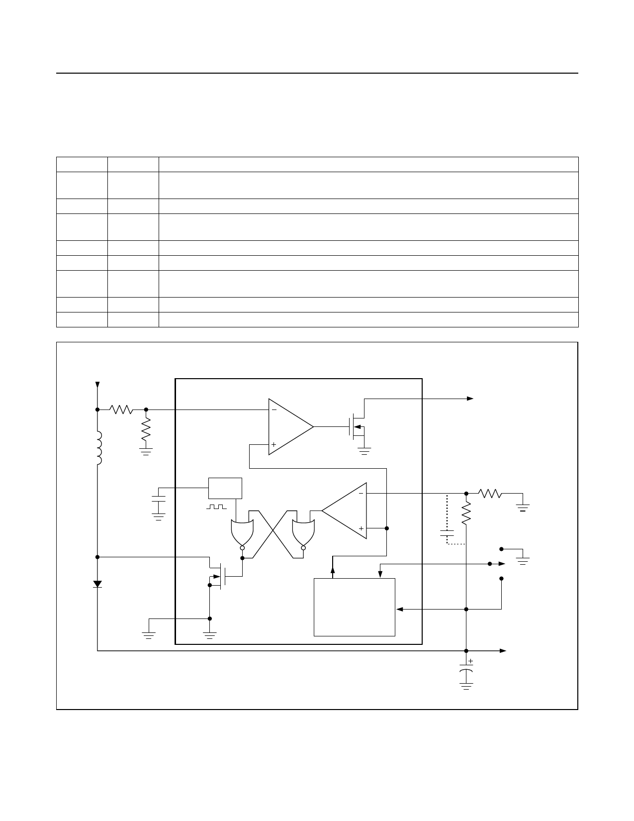
Figure 1. Single-Supply Operation
www.maximintegrated.com
Maxim Integrated │ 5
Share Link: 