APL1117A15VE-TRG データシートの表示(PDF) - Anpec Electronics
部品番号
コンポーネント説明
メーカー
APL1117A15VE-TRG Datasheet PDF : 13 Pages
| |||
APL1117A
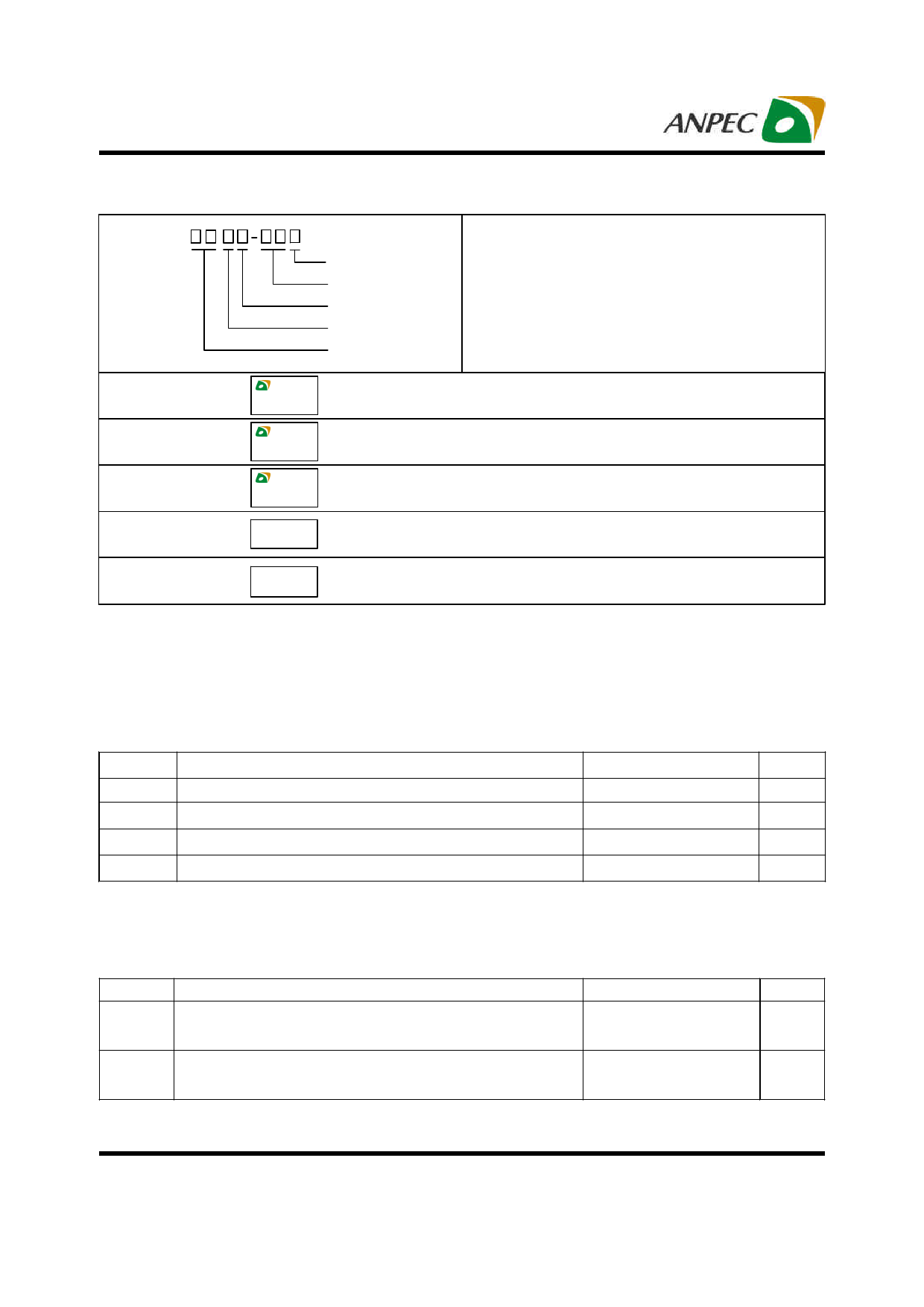
Ordering and Marking Information
APL1117A
Assembly Material
Handling Code
Temperature Range
Package Code
Voltage Code
Package Code
U : TO-252-3 V : SOT-223
Temperature Range
E : -20 to 70 oC
Handling Code
TR : Tape & Reel
Voltage Code
12 : 1.2V 15 : 1.5V Blank : Adjustable Version
Assembly Material
G : Halogen and Lead Free Device
APL1117A U :
APL1117A
XXXXX
XXXXX - Date Code
APL1117A 12U :
APL1117A
XXXXX 12
XXXXX - Date Code
APL1117A 15U :
APL1117A V :
APL1117A
XXXXX 15
APL1117A
XXXXX
XXXXX - Date Code
XXXXX - Date Code
APL1117A 15V :
APL1117A
XXXXX15
XXXXX - Date Code
Note: ANPEC lead-free products contain molding compounds/die attach materials and 100% matte tin plate termination finish; which
are fully compliant with RoHS. ANPEC lead-free products meet or exceed the lead-free requirements of IPC/JEDEC J-STD-020D for
MSL classification at lead-free peak reflow temperature. ANPEC defines “Green” to mean lead-free (RoHS compliant) and halogen
free (Br or Cl does not exceed 900ppm by weight in homogeneous material and total of Br and Cl does not exceed 1500ppm by
weight).
Absolute Maximum Ratings (Note 1)
Symbol
Parameter
Rating
Unit
VIN
DC Supply Voltage
TJ
Maximum Junction Temperature
-0.3 to 13
V
150
°C
TSTG Storage Temperature Range
-65 to +150
°C
TSDR Maximum Lead Soldering Temperature, 10 Seconds
260
°C
Note 1: Absolute Maximum Ratings are those values beyond which the life of a device may be impaired. Exposure to absolute
maximum rating conditions for extended periods may affect device reliability.
Thermal Characteristics (Note 2)
Symbol
Parameter
Typical Value
Unit
Junction to Ambient Thermal Resistance (Copper Area 10mmx10mm)
θJA
TO-252-3
55
SOT-223
70
oC/W
Junction to Case Thermal Resistance
θJC
TO-252-3
10
SOT-223
15
oC/W
Note 2 : The maximum allowable power dissipation at any TA (ambient temperature) is calculated using:PD (max) = (TJ – TA) / θJA; TJ =
125°C. Exceeding the maximum allowable power dissipation will result in excessive die temperature.
Copyright © ANPEC Electronics Corp.
2
Rev. A.4 - May., 2010
www.anpec.com.tw
Share Link: 