ARM2815TEM データシートの表示(PDF) - International Rectifier
部品番号
コンポーネント説明
メーカー
ARM2815TEM Datasheet PDF : 13 Pages
| |||
ARM28XXT Series
1
+Input
EMI
Filter
Under-Voltage
Detector
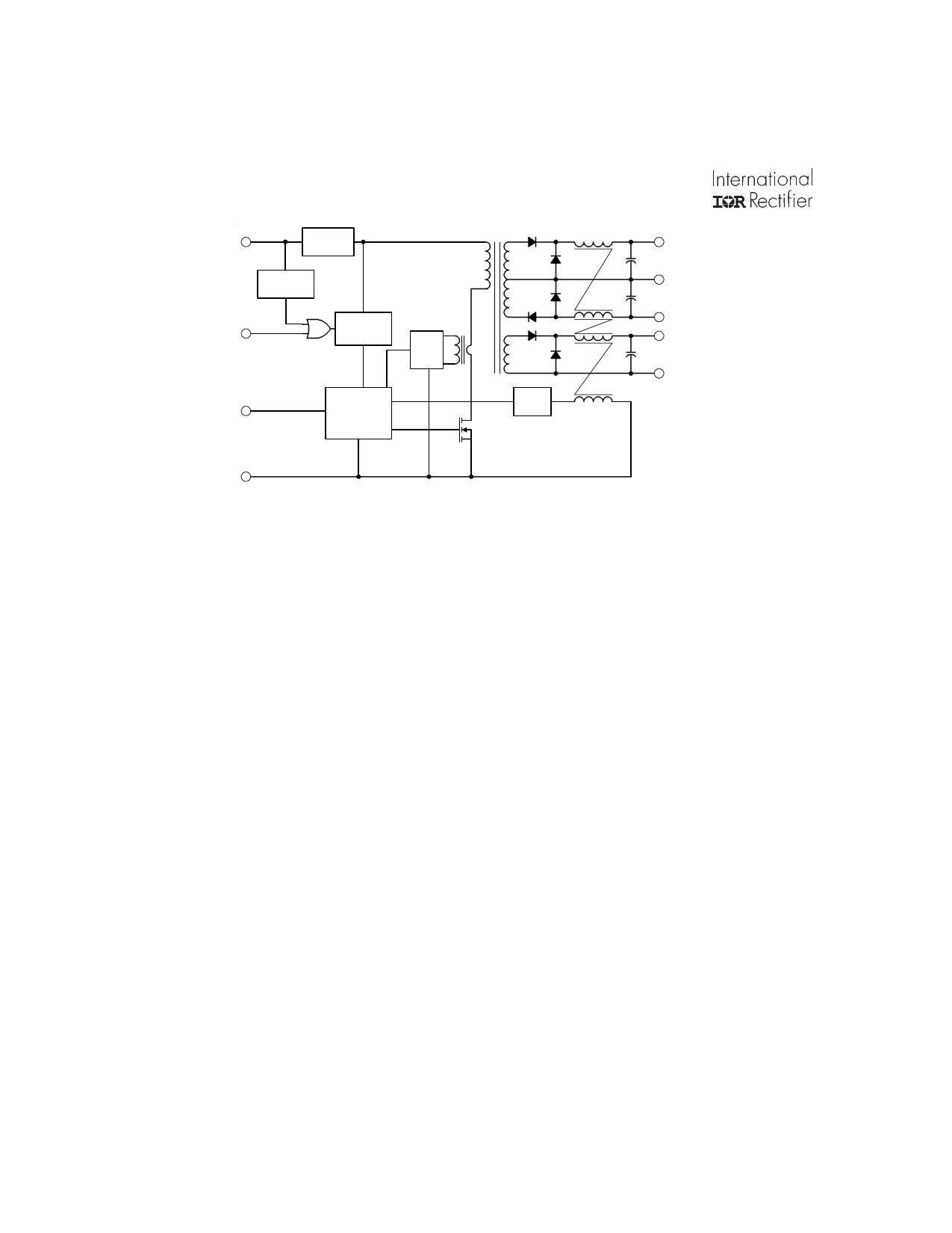
Figure I. Block Diagram
3
Enable
Primary Bias
& Reference
Short
Circuit
4
Sync In
Pulse Width
Modulator
Sample
Hold
11 +15 Vout
Dual
Output
10
Return
9 -15 Vout
Dual
13 +5 Vdc
Output
14 Output
Return
Input
Return
2
Circuit Description and Application Information Operating Guidelines
The ARM28XXT series of converters have been designed
using a single ended forward switched mode converter
topology. (refer to Figure I.) Single ended topologies enjoy
some advantage in radiation hardened designs in that they
eliminate the possibility of simultaneous turn on of both
switching elements during a radiation induced upset; in
addition, single ended topologies are not subject to
transformer saturation problems often associated with
double ended implementations.
The design incorporates an LC input filter to attenuate
input ripple current. A low overhead linear bias regulator
is used to provide bias voltage for the converter primary
control logic and a stable, well regulated reference for the
error amplifier. Output control is realized using a wide band
discrete pulse width modulator control circuit incorporating
a unique non-linear ramp generator circuit. This circuit
helps stabilize loop gain over variations in line voltage for
superior output transient response. Nominal conversion
frequency has been selected as 250 KHz to maximize
efficiency and minimize magnetic element size.
Output voltages are sensed using a coupled inductor and
a patented magnetic feedback circuit. This circuit is
relatively insensitive to variations in temperature, aging,
radiation and manufacturing tolerances making it
particularly well suited to radiation hardened designs. The
control logic has been designed to use only radiation
tolerant components, and all current paths are limited with
series resistance to limit photo currents.
The circuit topology used for regulating output voltages in
the ARM28XXT series of converters was selected for a
number of reasons. Significant among these is the ability
to simultaneously provide adequate regulation to three
output voltages while maintaining modest circuit complexity.
These attributes were fundamental in retaining the high
reliability and insensitivity to radiation that characterizes
device performance. Use of this topology dictates that the
user maintain the minimum load specified in the electrical
tables on each output. Attempts to operate the converter
without a load on any output will result in peak charging to
an output voltage well above the specified voltage regulation
limits, potentially in excess of ratings, and should be
avoided. Output loads that are less than specification
minimums will result in regulation performance outside the
limits presented in the tables. In most practical applications,
this lower bound on the load range does not present a
serious constraint; however the user should be mindfull of
the results. Characteristic curves illustrating typical
regulation performance are shown in Figures VII, VIII and IX.
Thermal Considerations
The ARM series of converters is capable of providing
relatively high output power from a package of modest
volume. The power density exhibited by these devices is
obtained by combining high circuit efficiency with effective
methods of heat removal from the die junctions. Good
design practices have effectively addressed this
requirement inside the device. However when operating
at maximum loads, significant heat generated at the die
Other key circuit design features include short circuit
protection, undervoltage lockout and an external
synchronization port permitting operation at an externally
set clock rate.
junctions must be carried away by conduction from the
base. To maintain case temperature at or below the
specified maximum of 125°C, this heat can be transferred
by attachment to an appropriate heat dissipater held in
intimate contact with the converter base-plate.
6
www.irf.com
Share Link: 