AS1341-BTDT(2007) データシートの表示(PDF) - austriamicrosystems AG
部品番号
コンポーネント説明
メーカー
AS1341-BTDT Datasheet PDF : 16 Pages
| |||
AS1341
Data Sheet - Application Information
9 Application Information
Adjusting Output Voltage
The AS1341 feedback input features dual-mode operation. Connect FB to GND for the 5.0V preset output voltage.
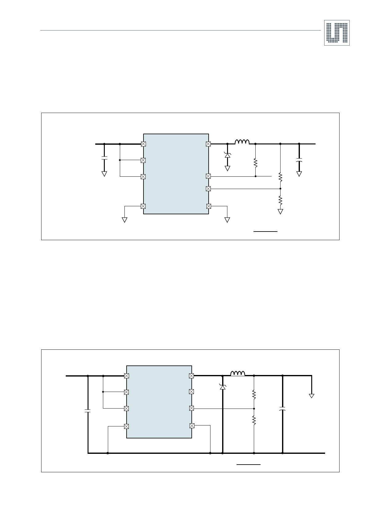
Adjust the output voltage by connecting a voltage-divider from the output to GND (Figure 4).
Figure 22. Adjustable Output Voltage Circuit
4.5 to
20V
CIN
5
IN
7
SHDNN
6
ILIMIT
2
GND
AS1341
4
LX
D1
3
POK
1
FB
8
OUT
L1
RPULL
1.25V
to VIN
+
COUT
R1
R2
Indicates High-Power Trace
Select a value for R2 between 10k and 1MΩ.
Calculate R1 as:
R1
=
R2
⋅
⎛
⎝
V-----O----U----T-
VFB
–
1⎠⎞
(EQ 2)
Where:
VFB = 1.25V.
VOUTPUT may range from 1.25V to VIN.
Setting Current Limit
The AS1341 adjustable peak current limit is set by connecting ILIMIT as shown in Table 4.
Table 4. Setting Peak Current Limit
Current Limit ILIMIT Connected To
700mA
GND
1400mA
IN
The current limit chosen should reflect the maximum load current. The maximum output current is half of the peak cur-
rent limit. Choosing a lower current limit allows using an inductor with a lower current rating, however, it requires a
higher inductance (see Inductor Selection on page 10) and does not allow for reduced inductor package size.
Inductor Selection
The AS1341 operates with a wide range of inductance values. For most applications, values between 10µH and 47µH
work best with the controller’s high switching frequency. Larger inductor values will reduce the switching frequency and
thereby improve efficiency and EMI.
Note: The four key factors in inductor selection are inductance value, saturation rating, series resistance, and size.
www.austriamicrosystems.com
Revision 1.00
10 - 16
Share Link: 