AS1341-BTDT(2007) データシートの表示(PDF) - austriamicrosystems AG
部品番号
コンポーネント説明
メーカー
AS1341-BTDT Datasheet PDF : 16 Pages
| |||
AS1341
Data Sheet - Application Information
The trade-off for improved efficiency is a higher output ripple and slower transient response. On the other hand, low-
value inductors respond faster to transients, improve output ripple, offer smaller physical size, and minimize cost. If the
inductor value is too small, the peak inductor current exceeds the current limit due to current-sense comparator propa-
gation delay, potentially exceeding the inductor’s current rating. Calculate the minimum inductance value as follows:
LMIN = ((VINMAX - VOUTPUT) x tONMIN/ILXPEAK
(EQ 3)
Where:
tONMIN = 1µs
The inductor saturation current rating must be greater than the peak switch current limit, plus the overshoot due to the
250ns current-sense comparator propagation delay. Saturation occurs when the magnetic flux density of the inductor
reaches the maximum level the core can support and the inductance starts to fall. Choose an inductor with a saturation
rating greater than IPEAK in the following equation:
IPEAK = (ILXPEAK + (VIN - VOUTPUT) x 250ns)/L
(EQ 4)
Inductor series resistance affects both efficiency and dropout voltage (see Dropout Voltage on page 9). High series
resistance limits the maximum current available at lower input voltages, and increases the dropout voltage. For opti-
mum performance, select an inductor with the lowest possible DC resistance that fits in the allotted dimensions.
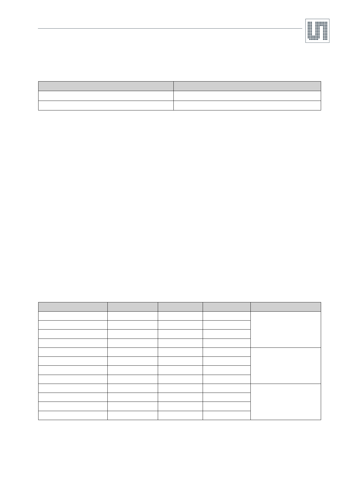
Table 5. Recommended Inductors
Part Number
MSS6132-103ML
LPS4018-472ML
MSS6132-393ML
LPS4018-223ML
CDRH6D28NP-150
CDRH5D18NP-4R1
CDRH6D28NP-470
CDRH5D18NP-220
LQH66SN-100M03
LQH55DN-150M03
LQH66SN-470M03
LQH55DN-470M03
L
10µH
4.7µH
39µH
22µH
15µH
4.1µH
47µH
22µH
10µH
15µH
47µH
47µH
DCR
85mΩ
125mΩ
345mΩ
360mΩ
62mΩ
57mΩ
176mΩ
215mΩ
36mΩ
150mΩ
170mΩ
400mΩ
Current Rating
1.4A
1.8A
0.8A
0.7A
1.4A
1.95A
0.8A
0.8A
1.6A
1.4A
0.8A
0.8A
Circuit
1, 4, 5
2, 5
3, 5
4, 5
1, 5
2, 5
3, 5
4, 5
1, 5
1, 5
3, 5
3, 5
Manufacturer
Coilcraft
www.coilcraft.com
Sumida
www.sumida.com
Murata
www.murata.com
Maximum Output Current
The AS1341 output current determines the regulator’s switching frequency. When the converter approaches continu-
ous mode, the output voltage falls out of regulation. For the typical application, the maximum output current is approxi-
mately:
ILOADMAX = 1/2 x ILXPEAKMIN
(EQ 5)
For low-input voltages, the maximum on-time may be reached and the load current is limited by:
ILOAD = (1/2 x (VIN - VOUT) x 10µs)/L
(EQ 6)
www.austriamicrosystems.com
Revision 1.00
11 - 16
Share Link: 