24C21 データシートの表示(PDF) - Atmel Corporation
部品番号
コンポーネント説明
メーカー
24C21 Datasheet PDF : 13 Pages
| |||
AT24C21
Functional Description
The AT24C21 has two modes of operation: the Transmit-
Only Mode and the Bidirectional Mode. There is a separate
2-wire protocol to support each mode, each having a sepa-
rate clock input (SCL and VCLK) and both modes sharing a
common Bidirectional data line (SDA). The AT24C21
enters the Transmit-Only Mode upon powering up the
device. In this mode, the device transmits data on the SDA
pin upon a clock signal on the VCLK pin. The device will
remain in the Transmit-Only Mode until a valid high-to-low
transition takes place on the SCL pin. The device will
switch into the Bidirectional Mode when a valid transition
on the SCL pin is recognized. Once the device has transi-
tioned to the Bidirectional Mode, there is no way to return to
the Transmit-Only Mode, except to power down (reset) the
device.
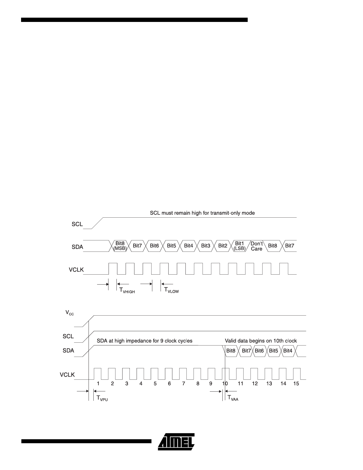
Transmit-Only Mode (DDC1)
The AT24C21 will power up in the Transmit-Only Mode. In
this mode, the device will output one bit of data on the SDA
pin on each rising edge on the VCLK pin. Data is transmit-
ted in 8 bit words with the most significant bit first. Each
Figure 1. Transmit-Only Mode
word is followed by a 9th “don't care” bit which will be in
high impedance state (refer to Figure 1). The AT24C21 will
continuously cycle through the entire memory array in
incremental sequence as long a VCLK is present and no
falling edges on SCL are received. When the maximum
address (7FH) is reached, the output will wrap around to
the zero location (00H) and continue. The Bidirectional
mode clock (SCL) pin must be held high for the device to
remain in the Transmit-Only mode.
Upon power-up, the AT24C21 will not output valid data until
it has been initialized. During initialization, data will not be
available until after the first nine clocks are sent to the
device (refer to Figure 2). The starting address for the
Transmit-Only mode can be determined during initializa-
tion. If the SDA pin is held high during the first eight clocks
(refer to Figure 2), the starting address will be 7FH. If the
SDA pin is low during the first eight clocks, the starting
address will be 00H. During the ninth clock, SDA should be
in high impedance.
Figure 2. Device Initialization for Transmit-Only Mode
5
Share Link: 