NX25F641C-3T データシートの表示(PDF) - NexFlash -> Winbond Electronics
部品番号
コンポーネント説明
メーカー
NX25F641C-3T Datasheet PDF : 23 Pages
| |||
NX25F641C
Command Set
The NX25F641C has a powerful command set that is fully
controlled through the SPI bus. Command relationships
are shown in Figure 4 and a list of commands and their
associated address, status, clock, and data bytes are
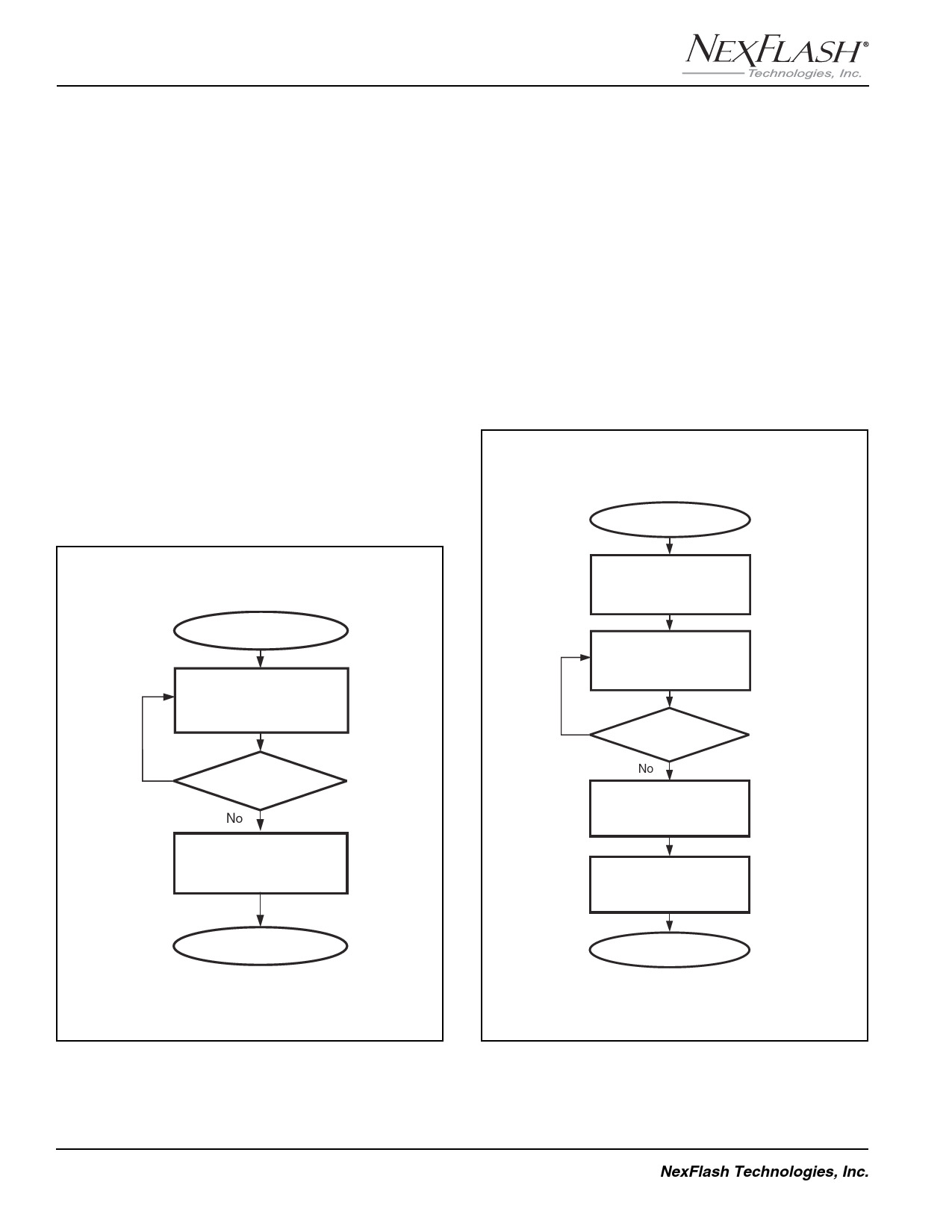
shown in the Command Set Table on page 13. Flow
diagrams for writing to a sector and reading from a sector
are shown in Figures 7 and 8. Detailed clock timing of the
Write to Sector using SRAM, Transfer Sector to SRAM
and Read SRAM command sequences are shown in
Figures 9, 10, 11 and 12.
After power up, a device enters an idle state that will main-
tain until CS pin is asserted low. Chip reset is defined as a
low to high transition of CS. Thus, to reset the chip at power
on, a high to low to high transition is required. A command
may start after a high to low transition of CS. When a
command is started, CS needs to stay low for the
duration of the command and data.
Start Read Sector Routine
Read Status Register for
Ready/Busy Status
(ST15)
(Command: 84H)
Yes
Busy ?
No
Read Data From SRAM-0/1
(Command: 50H/52H)
Return
Start Write Sector Routine
Write Enable Flash Array
(Command: 06H)
Read Status Register for
Read/Busy Status
(ST15, ST14, ST13)
(Command: 84H)
Yes
Busy ?
No
Write 528 Bytes Data
To Sector Using SRAM-0/1
(Command: F3H/94H)
(Optional)
Write-Disable Flash Array
(Command: 04H)
Return
Figure 7. Read data from sector
Figure 8. Write data to sector (Erase + Program)
12
NexFlash Technologies, Inc.
PRELIMINARY NXSF032A-0502
05/06/02 ©
Share Link: 