ATA6622C(2014) データシートの表示(PDF) - Atmel Corporation
部品番号
コンポーネント説明
メーカー
ATA6622C Datasheet PDF : 29 Pages
| |||
4.4 Fail-safe Mode
The device automatically switches to Fail-safe Mode at system power-up. The voltage regulator is switched on (see Figure
5-1 on page 13). The NRES output switches to low for tres = 4ms and gives a reset to the microcontroller. LIN communication
is switched off. The IC stays in this mode until EN is switched to high. The IC then changes to Normal Mode. A power down
of VBatt (VS < 3.7V) during Silent or Sleep Mode switches the IC into Fail-safe Mode after power up. A low at NRES switches
into Fail-safe Mode directly. During Fail-safe Mode the TXD pin is an output and signals the last wake-up source.
4.5 Unpowered Mode
If you connect battery voltage to the application circuit, the voltage at the VS pin increases according to the block capacitor
(see Figure 5-1 on page 13). After VS is higher than the VS undervoltage threshold VSth, the IC mode changes from
Unpowered Mode to Fail-safe Mode. The VCC output voltage reaches its nominal value after tVCC. This time, tVCC, depends
on the VCC capacitor and the load.
The NRES is low for the reset time delay treset. During this time, treset, no mode change is possible.
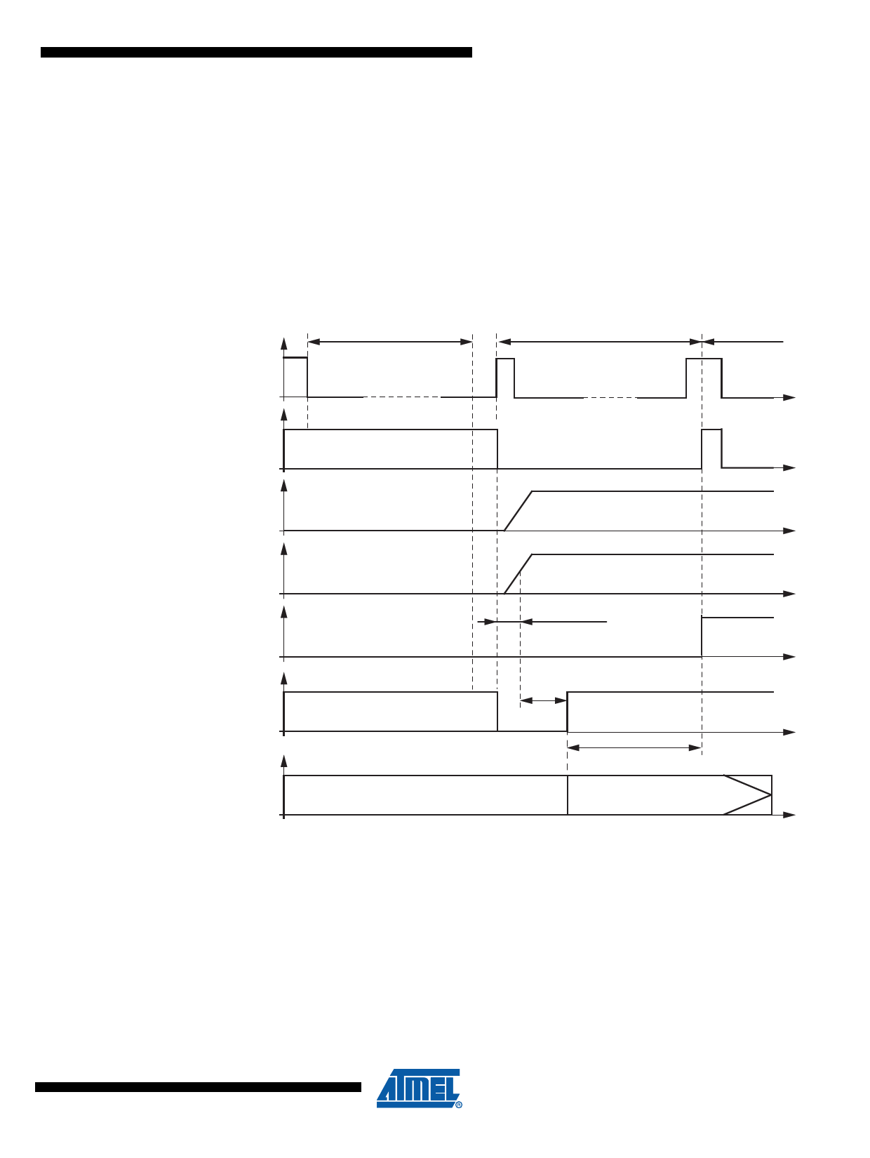
Figure 4-5. LIN Wake Up from Sleep Mode
Bus wake-up filtering time
tbus
Fail-safe Mode
Normal Mode
LIN bus
RXD
Low
Low
TXD
VCC
voltage
regulator
EN
NRES
Watchdog
Off state
Low
Watchdog off
On state
Regulator wake-up time
Reset
time
EN High
Microcontroller
start-up time delay
Start watchdog lead time td
ATA6622C/ATA6624C/ATA6626C [DATASHEET]
11
4986O–AUTO–10/14
Share Link: 