ATMEGA1284 データシートの表示(PDF) - Atmel Corporation
部品番号
コンポーネント説明
メーカー
ATMEGA1284
Atmel Corporation

ATMEGA1284 Datasheet PDF : 32 Pages
| |||
164A/164PA/324A/324PA/644A/644PA/1284/1284P
16/32/64/128K bytes of In-System Programmable Flash with Read-While-Write capabilities,
512B/1K/2K/4K bytes EEPROM, 1/2/4/16K/ bytes SRAM, 32 general purpose I/O lines, 32 gen-
eral purpose working registers, Real Time Counter (RTC), three flexible Timer/Counters with
compare modes and PWM, 2 USARTs, a byte oriented 2-wire Serial Interface, a 8-channel, 10-
bit ADC with optional differential input stage with programmable gain, programmable Watchdog
Timer with Internal Oscillator, an SPI serial port, IEEE std. 1149.1 compliant JTAG test interface,
also used for accessing the On-chip Debug system and programming and six software select-
able power saving modes. The Idle mode stops the CPU while allowing the SRAM,
Timer/Counters, SPI port, and interrupt system to continue functioning. The Power-down mode
saves the register contents but freezes the Oscillator, disabling all other chip functions until the
next interrupt or Hardware Reset. In Power-save mode, the asynchronous timer continues to
run, allowing the user to maintain a timer base while the rest of the device is sleeping. The ADC
Noise Reduction mode stops the CPU and all I/O modules except Asynchronous Timer and
ADC, to minimize switching noise during ADC conversions. In Standby mode, the Crystal/Reso-
nator Oscillator is running while the rest of the device is sleeping. This allows very fast start-up
combined with low power consumption. In Extended Standby mode, both the main Oscillator
and the Asynchronous Timer continue to run.
The device is manufactured using Atmel’s high-density nonvolatile memory technology. The On-
chip ISP Flash allows the program memory to be reprogrammed in-system through an SPI serial
interface, by a conventional nonvolatile memory programmer, or by an On-chip Boot program
running on the AVR core. The boot program can use any interface to download the application
program in the application Flash memory. Software in the Boot Flash section will continue to run
while the Application Flash section is updated, providing true Read-While-Write operation. By
combining an 8-bit RISC CPU with In-System Self-Programmable Flash on a monolithic chip,
the Atmel ATmega164A/164PA/324A/324PA/644A/644PA/1284/1284P is a powerful microcon-
troller that provides a highly flexible and cost effective solution to many embedded control
applications.
The ATmega164A/164PA/324A/324PA/644A/644PA/1284/1284P AVR is supported with a full
suite of program and system development tools including: C compilers, macro assemblers, pro-
gram debugger/simulators, in-circuit emulators, and evaluation kits.
2.2 Comparison Between ATmega164A, ATmega164PA, ATmega324A, ATmega324PA,
ATmega644A, ATmega644PA, ATmega1284 and ATmega1284P
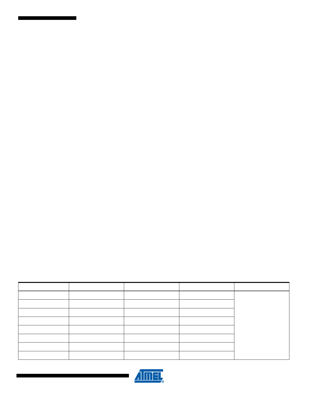
Table 2-1. Differences between ATmega164A, ATmega164PA, ATmega324A, ATmega324PA, ATmega644A,
ATmega644PA, ATmega1284 and ATmega1284P
Device
Flash
EEPROM
RAM
Units
ATmega164A
16 K
512
1K
ATmega164PA
16 K
512
1K
ATmega324A
32 K
1K
2K
ATmega324PA
32 K
1K
2K
bytes
ATmega644A
64 K
2K
4K
ATmega644PA
64 K
2K
4K
ATmega1284
128 K
4K
16 K
ATmega1284P
128 K
4K
16 K
6
8272AS–AVR–01/10
Share Link: