TC820CLW データシートの表示(PDF) - Microchip Technology
部品番号
コンポーネント説明
メーカー
TC820CLW Datasheet PDF : 28 Pages
| |||
TC820
3.2.7 10:1 RANGE CHANGE
The analog input full scale range can be changed with
the RANGE/FREQ input. Normally, RANGE/FREQ is
held low by an internal pull-down. Connecting this pin
to VS+ will increase the full scale voltage by a factor
of 10. No external component changes are required.
The RANGE/FREQ input operates by changing the
integrate period. When RANGE/FREQ is connected to
VDD, the signal integration phase of the conversion is
reduced by a factor of 10 (i.e., from 2000 counts to 200
counts).
For the TC820, the 10:1 range change will result in ±4V
full scale. This full scale range will exceed the Common
mode range of the input buffer when operating from a
9V battery. If range changing is required for the TC820,
a higher supply voltage can be provided, or the input
voltage can be divided by 2 externally.
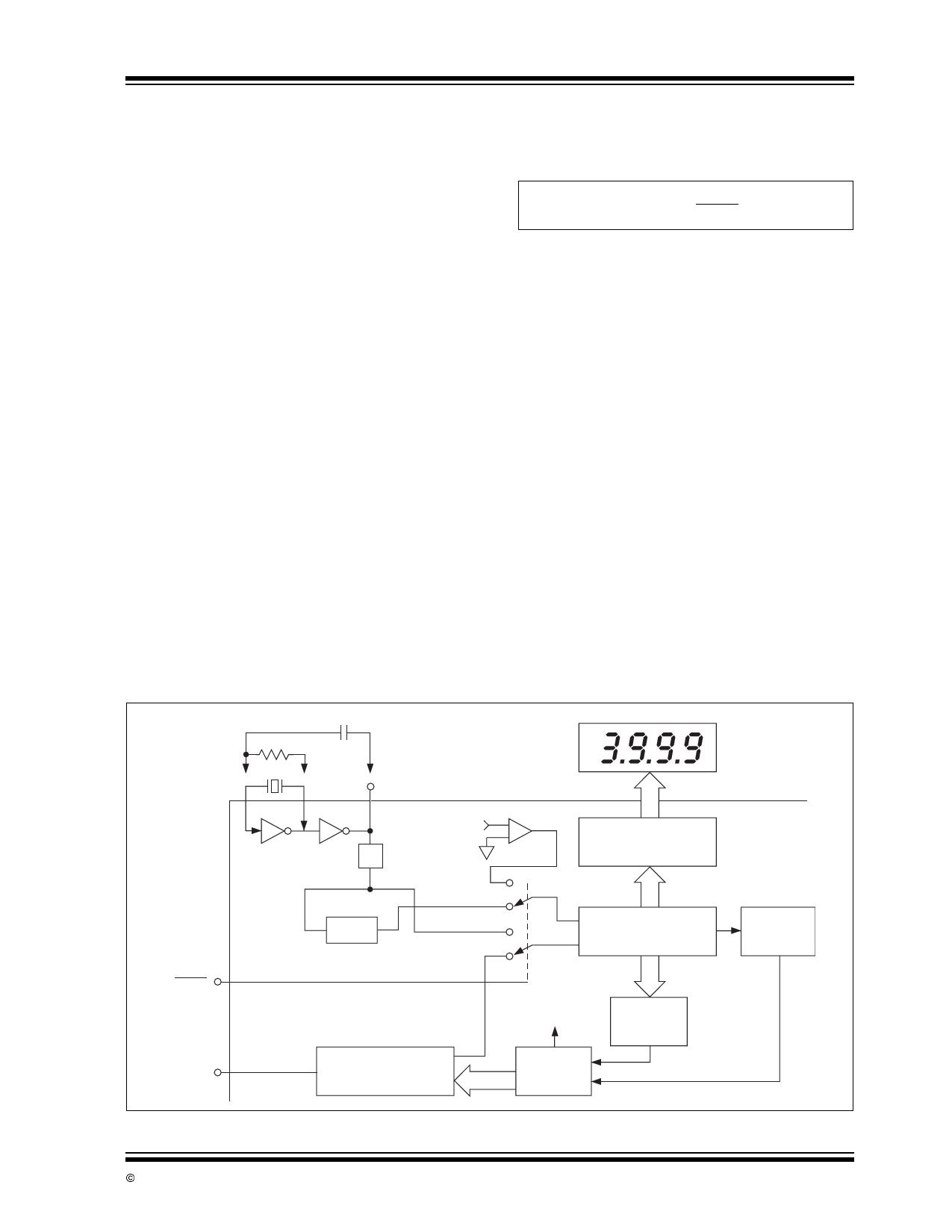
3.3 Frequency Counter
In addition to serving as an analog-to-digital converter,
the TC820 internal counter can also function as a fre-
quency counter (Figure 3-3). In the Counter mode,
pulses at the RANGE/FREQ input will be counted and
displayed.
The frequency counter derives its time-base from the
clock oscillator. The counter time-base is:
EQUATION 3-5:
tCOUNT = FOSC
40,000
Thus, the counter will operate with a 1-second time-
base when a 40kHz oscillator is used. The frequency
counter accuracy is determined by the oscillator accu-
racy. For accurate frequency measurements, a crystal
oscillator is recommended.
The frequency counter will automatically select the
proper range. Auto-range operation extends over four
decades, from 3.999kHz to 3.999MHz. Decimal points
are set automatically in the Frequency mode (Figure 3-4).
The logic switching levels of the RANGE/FREQ input
are CMOS levels. For best counter operation, an exter-
nal buffer is recommended. See the applications sec-
tion for details.
3.4 Logic Probe
The TC820 can also function as a simple logic probe
(Figure 3-5). This mode is selected when the LOGIC
input is high. Two dual purpose pins, which normally
control the decimal points, are used as logic inputs.
Connecting either input to a logic high level will turn on
the corresponding LCD annunciator. When the "low"
annunciator is on, the buzzer will be on. As with the fre-
quency counter input, external level shifters/buffers are
recommended for the logic probe inputs.
FIGURE 3-3:
TC820 COUNTER OPERATION
LCD
Clock
Oscillator
TC820
From Integrator
of A/D Converter
÷2
Comparator
Data Latch, Peak Hold
Register, LCD
Decoder/Drivers
FREQ/
VOLTS
÷20,000
A/D Converter/Frequency
Counter Select
A/D Converter
Frequency Counter
Enable
3-3/4 Digit Counter
Count
Overflow
To Decimal
Point Drivers
Under Range
Control
RANGE/
FREQ
Frequency Input
Programmable
Divider
( ÷1, 10, 100, 1000)
Auto-Range
Control
Over Range
Detect
© 2002 Microchip Technology Inc.
DS21476B-page 11
Share Link: 