BYV26DGP データシートの表示(PDF) - Vishay Semiconductors
部品番号
コンポーネント説明
メーカー
BYV26DGP Datasheet PDF : 5 Pages
| |||
BYV26DGP, BYV26EGP
Vishay General Semiconductor
ELECTRICAL CHARACTERISTICS (TA = 25 °C unless otherwise noted)
PARAMETER
TEST CONDITIONS
SYMBOL
BYV26DGP
BYV26EGP
Minimum avalanche
breakdown voltage
100 μA
VBR
900
1100
Maximum instantaneous
forward voltage
1.0 A
TJ = 25 °C
TJ = 175 °C
VF
2.5
1.3
Maximum DC reverse current at
rated DC blocking voltage
TA = 25 °C
IR
TA = 165 °C
5.0
150
Max. reverse recovery time
IF = 0.5 A, IR = 1.0 A,
Irr = 0.25 A
trr
75
Typical junction capacitance
4.0 V, 1 MHz
CJ
15
UNIT
V
V
μA
ns
pF
THERMAL CHARACTERISTICS (TA = 25 °C unless otherwise noted)
PARAMETER
SYMBOL
BYV26DGP
BYV26EGP
UNIT
Typical thermal resistance
RJA (1)
70
RJL (2)
16
°C/W
Notes
(1) Thermal resistance from junction to ambient at 0.375" (9.5 mm) lead length, mounted on PCB with 0.5" x 0.5" (12 mm x 12 mm) copper pads
(2) Thermal resistance from junction to lead at 0.375" (9.5 mm) lead length with both leads attached to heatsink
ORDERING INFORMATION (Example)
PREFERRED P/N
UNIT WEIGHT (g) PREFERRED PACKAGE CODE
BYV26EGP-E3/54
0.428
54
BYV26EGP-E3/73
0.428
73
BYV26EGPHE3/54 (1)
0.428
54
BYV26EGPHE3/73 (1)
0.428
73
Note
(1) AEC-Q101 qualified
BASE QUANTITY
4000
2000
4000
2000
DELIVERY MODE
13" diameter paper tape and reel
Ammo pack packaging
13" diameter paper tape and reel
Ammo pack packaging
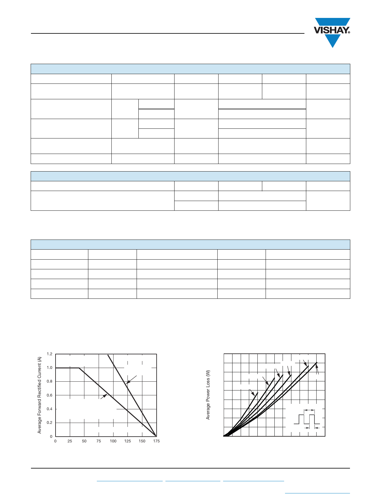
RATINGS AND CHARACTERISTICS CURVES
(TA = 25 °C unless otherwise noted)
1.2
Resistive or
Inductive Load
1.0
0.8
TL = Lead Temperature
Lead Mounted
on Heatsinks
0.6
Mounted on P.C.B.
0.4
0.375" (9.5 mm) Lead Length on
0.47" x 0.47" (12 mm x 12 mm)
Copper Pads
0.2
TA = Ambient Temperature
0
0
25 50 75 100 125 150 175
Temperature (°C)
Fig. 1 - Maximum Forward Current Derating Curve
1.8
1.6
1.4
1.2
1.0
0.8
0.6
0.4
0.2
0
0
D = 0.8
D = 0.3 D = 0.5
D = 0.2
D = 1.0
D = 0.1
T
D = tp/T tp
0.2
0.4
0.6
0.8
1.0
1.2
Average Forward Current (A)
Fig. 2 - Forward Power Loss Characteristics
www.vishay.com
2
For technical questions within your region, please contact one of the following: Document Number: 88554
DiodesAmericas@vishay.com, DiodesAsia@vishay.com, DiodesEurope@vishay.com
Revision: 15-Mar-11
This datasheet is subject to change without notice.
THE PRODUCT DESCRIBED HEREIN AND THIS DATASHEET ARE SUBJECT TO SPECIFIC DISCLAIMERS, SET FORTH AT www.vishay.com/doc?91000
Share Link: 