L432V データシートの表示(PDF) - Niko Semiconductor
部品番号
コンポーネント説明
メーカー
L432V Datasheet PDF : 11 Pages
| |||
NIKO-SEM
1.24V Low-Voltage Adjustable
Precision Shunt Regulator
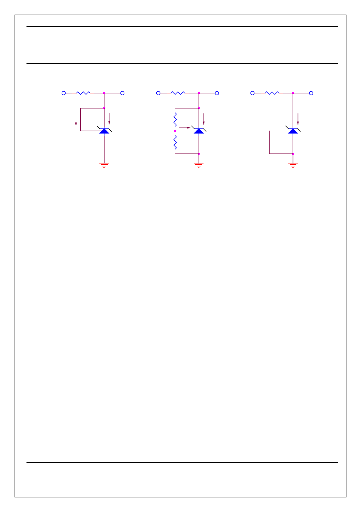
TEST CIRCUITS
VIN
VKA VIN
VKA VIN
I REF
IK
R1 I REF
IK
V REF
R2
L432
VKA
I K (OFF)
- TEST CIRCUIT 1 -
(VKA = VREF)
- TEST CIRCUIT 2 -
(VKA > VREF)
- TEST CIRCUIT 3 -
(OFF STATE CURRENT)
Applications Information – Stability
Selection of load capacitance when using
L432 as a shunt regulator
When the L432 is used as a shunt regulator,
two options for selection of CL are
recommended for optimal stability:
1. No load capacitance across the device,
decouple at the load.
2. Large capacitance across the device,
optional decoupling at the load.
The reason for this is that L432 exhibits
instability with capacitances in the range of
1nF to 1uf (approx.) at light cathode currents
(up to 3mA typical). The device is less stable
the lower the cathode voltage has been set for.
Therefore while the device will be perfectly
stable operating at a cathode current of 10mA
with a 0.1uF capacitor across it, it will oscillate
transiently during start-up as the cathode
current passes through the instability region.
Selecting a very low
(or preferably, no)capacitance, or alter-
natively a high capacitance (such as 10uF)
will avoid this issue altogether. Since the
user will probably wish to have local
decoupling at the load anyway, the most
cost effective method is to use no
capacitance at all directly across the
device. PCB trace/via resistance and
inductance prevent the local load de-
coupling from causing the oscillation during
the transient start-up phase. Note : if the
L432 is located right at the load, so the
load decoupling capacitor is directly across
it, then this capacitor will have to be
≦ 100pF or ≧ 1uF.
3
NOV-21-2001
Share Link: 