IRFF220 データシートの表示(PDF) - Intersil
部品番号
コンポーネント説明
メーカー
IRFF220 Datasheet PDF : 7 Pages
| |||
IRFF220
Source to Drain Diode Specifications
PARAMETER
SYMBOL
TEST CONDITIONS
MIN TYP MAX UNITS
Continuous Source to Drain Current
Pulse Source to Drain Current (Note 3)
ISD
ISDM
Modified MOSFET
Symbol Showing the
Integral Reverse P-N
Junction Rectifier
G
D
-
-
3.5
A
-
-
14
A
Source to Drain Diode Voltage (Note 2)
Reverse Recovery Time
Reverse Recovered Charge
VSD
trr
QRR
S
TJ = 25oC, ISD = 3.5A, VGS = 0V (Figure 13)
TJ = 150oC, ISD = 3.5A, dISD/dt = 100A/µs
TJ = 150oC, ISD = 3.5A, dISD/dt = 100A/µs
-
-
2.0
V
-
350
-
ns
-
2.3
-
µC
NOTES:
2. Pulse test: pulse width ≤ 300µs, duty cycle ≤ 2%.
3. Repetitive rating: pulse width limited by Max junction temperature. See Transient Thermal Impedance curve (Figure 3).
4. VDD = 20V, start TJ = 25oC, L = 12.5mH, RG = 50Ω, peak IAS = 3.5A (Figures 15, 16).
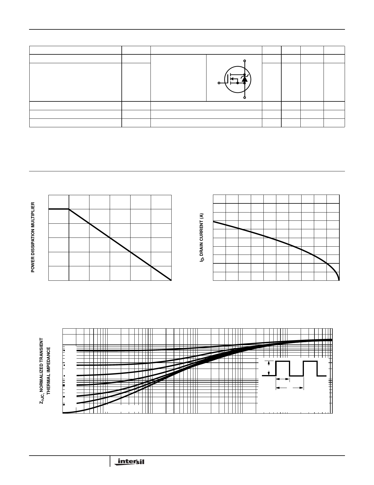
Typical Performance Curves
1.2
1.0
0.8
0.6
0.4
0.2
0
0
50
100
150
TC, CASE TEMPERATURE (oC)
FIGURE 1. NORMALIZED POWER DISSIPATION vs CASE
TEMPERATURE
5
4
3
2
1
0
25
50
75
100
125
150
TC, CASE TEMPERATURE (oC)
FIGURE 2. MAXIMUM CONTINUOUS DRAIN CURRENT vs
CASE TEMPERATURE
2
1.0
0.5
0.2
0.1
0.1
0.05
0.02
0.01
0.01
10-5
PDM
SINGLE PULSE
10-4
10-3
10-2
0.1
t1, SQUARE WAVE PULSE DURATION (s)
t1
t2
NOTES:
DUTY FACTOR: D = t1/t2
TJ = PDM x ZθJC x RθJC + TC
1
10
FIGURE 3. NORMALIZED MAXIMUM TRANSIENT THERMAL IMPEDANCE
3
Share Link: 