CDP1871 データシートの表示(PDF) - Intersil
部品番号
コンポーネント説明
メーカー
CDP1871 Datasheet PDF : 10 Pages
| |||
CDP1871A, CDP1871AC
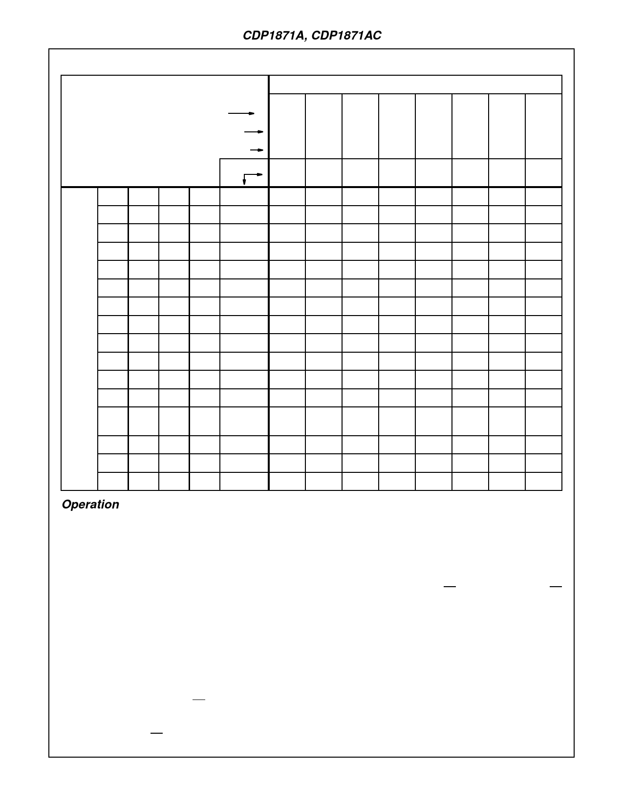
TABLE 4. HEXIDECIMAL VALUES OF ASCII CHARACTERS
MSD
b7
0
0
0
0
1
1
1
1
b6
0
0
1
1
0
0
1
1
BITS
b5
0
1
0
1
0
1
0
1
b4 b3 b2 b1
HEX
0
1
2
3
4
5
6
7
0
0
0
0
0
NUL DLE
SP
0
@
P
\
p
0
0
0
1
1
SOH DC1
!
1
A
Q
a
q
0
0
1
0
2
STX DC2
“
2
B
R
b
r
0
0
1
1
3
ETX DC3
#
3
C
S
c
s
0
1
0
0
4
EOT DC4
$
4
D
T
d
t
0
1
0
1
5
ENQ NAK
%
5
E
U
e
u
0
1
1
0
6
ACK SYN
&
6
F
V
f
v
0
1
1
1
LSD
1
0
0
0
7
BEL
ETB
/
7
G
W
g
w
8
BS
CAN
(
8
H
X
h
x
1
0
0
1
9
HT
EM
)
9
I
Y
i
y
1
0
1
0
A
LF
SUB
*
:
J
Z
j
z
1
0
1
1
B
VT
ESC
+
;
K
[
k
{
1
1
0
0
C
FF
FS
,
<
L
\
l
|
|
1
1
0
1
D
CR
GS
-
=
M
]
m
}
1
1
1
0
E
SO
RS
.
>
N
↑
n
~
1
1
1
1
F
SI
US
/
?
O
-
o
DEL
Operation
The CDP1871A is made up of two major sections: the
counter/scan-selection logic and the control logic (Figure 2).
The counter and scan-selection logic scans the keyboard
array using the drive lines (D1-D11) and the sense lines (S1-
S8). The outputs of the internal 5-stage scancounter are
conditionally encoded by the ALPHA, SHIFT, and CONTROL
inputs (Table 1, Table 3) and are used to drive the D1-D11
output lines high one at a time. Each D1-D11 output may
drive up to eight keys, which are sampled by the sense line
inputs (S1-S8). The S1-S8 inputs are enabled by the internal
3-stage scancounter.
outputs (C1 - C8) represent the ASCII and HEX key codes
and are used to drive the BUS 0 - BUS 7 outputs, which
interface directly to the CDP1800-Series data bus. The BUS
0 - BUS 7 outputs, which are normally three-stated, are
enabled by decoding the CS inputs during a CPU input
instruction (Table 2). The low-to-high transition of TPB during
the input instruction resets the DA output high. Once the DA
output has been reset, it cannot go low again until the
present key is released and a new keydown condition is
detected. (This prevents unwanted repeated keycode out-
puts which may be caused by fast software routines).
The control logic interfaces with the CDP1800-series I/O and
timing signals to establish timing and status conditions for
the CDP1871A.
The TPB input clocks the scancounters and is also used to
reset the Data Available output (DA). When a valid keydown
condition is detected on a sense line, the control logic inhib-
its the clock to the scancounters on the next low-to-high tran-
sition of TPB and the DA output is set low. The scancounter
After the depressed key is released and the debounce delay
(determined by RX, CX) has occurred, the scan clock inhibit
is removed, allowing the scancounters to advance on the fol-
lowing high-to-low transitions of TPB. This provides an N-key
lockout feature, which prevents the entry of erroneous codes
when two or more keys are pressed simultaneously. The first
key pressed in the scanning order is recognized, while all
other keys pressed are ignored until the first key is released
4-72
Share Link: 