CM3842 データシートの表示(PDF) - Unspecified
部品番号
コンポーネント説明
メーカー
CM3842 Datasheet PDF : 12 Pages
| |||
CM3842/3843
CURRENT MODE PWM CONTROLLER
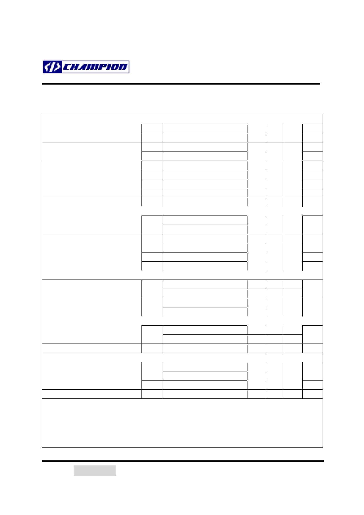
ELECTRICAL CHARACTERISTICS (Continued)
Error Amplifier Section
Input Bias Current
Input Voltage
Open Loop Voltage Gain
Unity Gain Bandwidth (note 8)
Power Supply Rejection Ratio
Output Sink Current
Output Source Current
High Output Voltage
Low Output Voltage
Output Section
Output Low Level
Output High Level
Rise Time (note 8)
Fall Time (note 8)
Under-Voltage Lockout Section
Start Threshold
Min. Operating Voltage
PWM Section
Maximum Duty Cycle
Minimum Duty Cycle
Total Standby Current
Startup Current
Operating Supply Current
Zener Voltage
IBIAS
VI(EA)
GVO
UGBW
PSRR
ISINK
ISOURCE
VOH
VOL
COMP = 2.5V
2V ≤ VO ≤ 4V
TJ = 25 OC
12V ≤ VCC ≤ 25V
VFB = 2.7V, COMP = 1.1V
VFB = 2.3V, COMP = 5.0V
VFB = 2.3V, RL = 15KΩ to GND
VFB = 2.7V, RL = 15KΩ to VREF
-0.1 -2
µA
2.42 2.50 2.58 V
65 90
dB
0.7 1
MHz
60 70
dB
2
7
mA
-0.5 -1.0
mA
5
6
V
0.7 1.1
V
VOL
ISINK = 20mA
ISINK = 200mA
VOH
ISOURCE = 20mA
ISOURCE = 200mA
tr
TJ = 25 OC, CL = 1nF
tf
TJ = 25 OC, CL = 1nF
0.1 0.4
V
1.4 2.2
13 13.5
V
12 13.0
50 150 ns
50 150 ns
VTH(ST)
CM3842
CM3843
CM3842
CM3843
14.5 16.0 17.5
V
7.8 8.4 9.0
8.5
10 11.5
V
7.0 7.6 8.2
CM3842/43
94 97 100
%
0
%
CM3842
CM3843
ICC
VFB = ISENSE = 0V
VZ
ICC = 25mA
0.2 0.35 mA
0.5 1.0
14 17 mA
30 35
V
note 7: Adjust VCC above the start threshold before setting at 15V
note 8: These parameters, although guaranteed, are not 100% tested in production prior to shipment
note 9: Parameters are measured at trip point of latch with VFB = 2V
note 10: Gain is measured between ISENSE and COMP with the input changing from 0V to 0.8V
2001/06/27 Advanced
Champion Microelectronic Corporation
Page 5
Share Link: 