CNA1007H(2008) データシートの表示(PDF) - Panasonic Corporation
部品番号
コンポーネント説明
メーカー
CNA1007H Datasheet PDF : 5 Pages
| |||
This product complies with the RoHS Directive (EU 2002/95/EC).
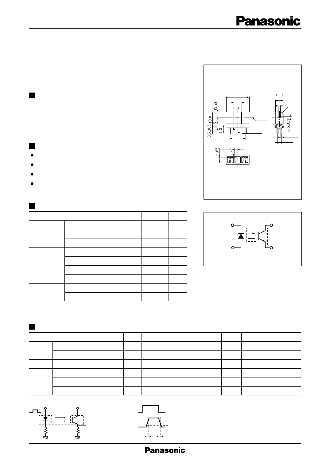
Transmissive Photosensors (Photo lnterrupters)
CNA1007H
Photo lnterrupter
For contactless SW and object detection
Overview
CNA1007H is a transmissive photosensor in which a high efficiency GaAs infrared light emitting diode is used as the light emitting
element, and a high sensitivity phototransistor is used as the light detecting element. The two elements are arranged so as to face each other,
and objects passing between them are detected.
Features
Highly precise position detection: 0.3 mm
Gap width: 5 mm
/ Horizontal slit type
The type directly attached to PCB (with a positioning pins)
e e) Absolute Maximum Ratings Ta = 25°C
c typ Parameter
Symbol Rating
Unit
n dle stage.ntinued Input
a elifecyc , disco (Light emitting diode)
Power dissipation *1
Forward current
Reverse voltage
PD
75
mW
IF
50
mA
VR
5
V
n u ct ped Collector-emitter voltage
rodu d ty (Base open)
VCEO
30
V
te tin urP tinue Output
fo on (Photo transistor)
Emitter-collector voltage
(Base open)
VECO
5
V
wing disc Collector current
IC
20
mA
in n follo ned Collector power dissipation *2
PC
100
mW
des , pla Operating ambient temperature
Topr
–25 to +85
°C
a o inclu type Storage temperature
Tstg –40 to +100 °C
c ued nce Note) *1: Input power derating ratio is 1.0 mW/°C at Ta ≥ 25°C
M is ntin tena *2: Output power derating ratio is 1.33 mW/°C at Ta ≥ 25°C
/Disco main Electrical-Optical Characteristics Ta = 25°C±3°C
ce pe, Parameter
Symbol
Conditions
D tenan ce ty Input
Reverse current
ain nan characteristics Forward voltage
M inte Output
Collector-emitter cutoff current
ma characteristics (Base open)
IR
VR = 3 V
VF IF = 20 mA
ICEO VCE = 10 V
laned Collector current
IC
VCC = 5 V, IF = 20 mA
(p Transfer
Collector-emitter saturation voltage VCE(sat) IF = 40 mA, IC = 1 mA
Min Typ Max Unit
10
µA
1.25 1.4
V
200
nA
0.5
10.0 mA
0.4
V
characteristics Rise time *
Fall time *
tr
VCC = 5 V, IC = 1 mA,
tf
RL = 100 W
5.0
µs
5.0
µs
Note) 1. Input and output are practiced by electricity.
2. This device is designed by disregarding radiation.
3. *: Switching time measurement circuit
Sig. in
50 Ω
VCC
(Input pulse)
Sig. out
RL
(Output pulse)
tr
tr : Rise time
90% tf : Fall time
10%
tf
Publication date: October 2008
SHG00016CED
1
Share Link: 