CS61582 データシートの表示(PDF) - Cirrus Logic
部品番号
コンポーネント説明
メーカー
CS61582 Datasheet PDF : 32 Pages
| |||
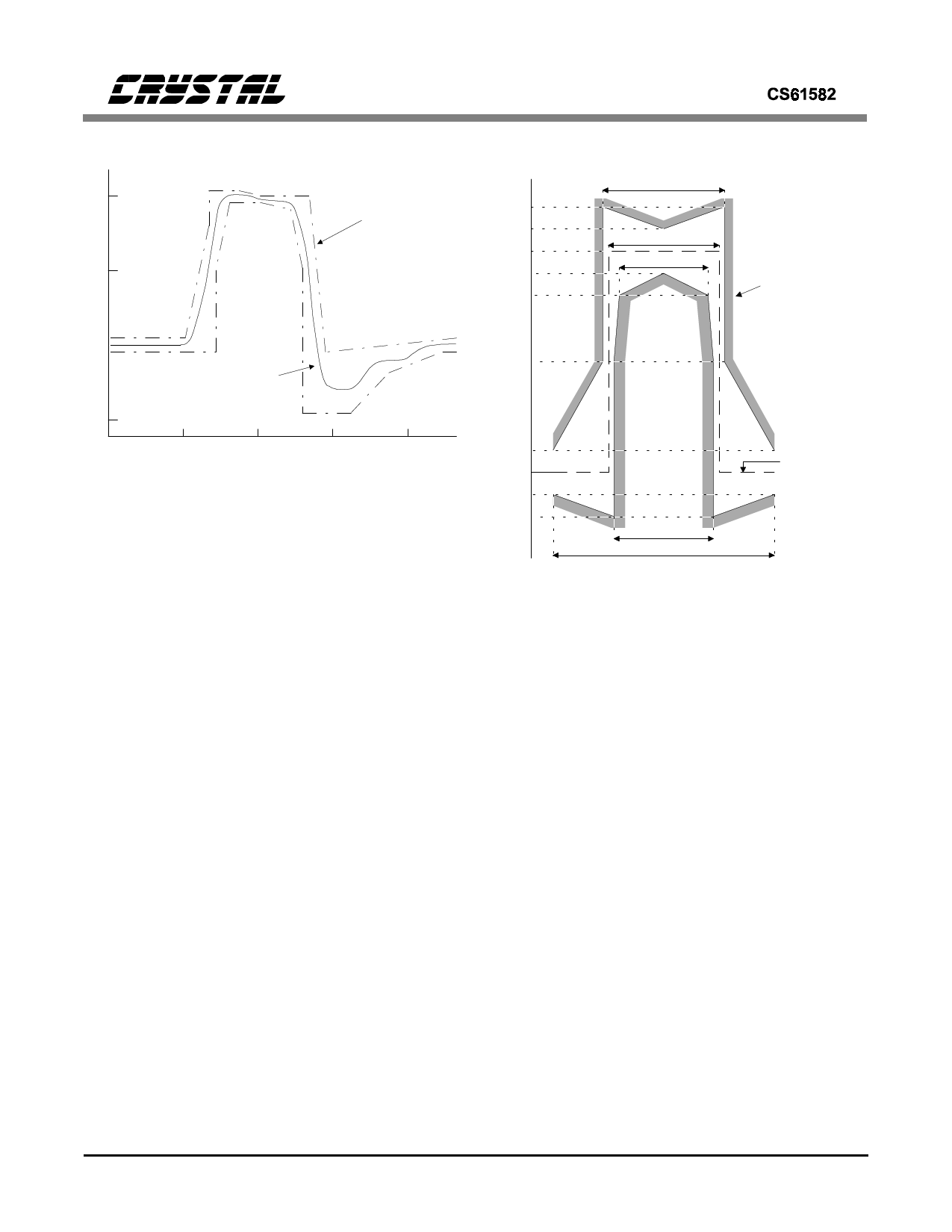
NORM ALIZED
A M P LIT U D E
1.0
0.5
ANSI T1.102
S P E C IF IC A T IO N
Percent of
nom inal
peak
voltage
120
110
100
90
80
269 ns
244 ns
194 ns
G .70 3
S P E C IF IC A T IO N
0
-0.5
0
CS61582
OUTPUT
PULSE SHAPE
250
500
750
TIM E (nanoseconds)
1000
Figure 5. Typical Pulse Shape at DSX-1 Cross Connect
matically adjusts the pulse width based on the
configuration selection.
The transmitter impedance changes with the line
length options in order to match the load imped-
ance (75Ω for E1 coax, 100Ω for T1, 120Ω for
E1 shielded twisted pair), providing a minimum
of 14 dB return loss for T1 and E1 frequencies
during the transmission of both marks and
spaces. This improves signal quality by minimiz-
ing reflections from the transmitter. Impedance
matching also reduces load power consumption
by a factor of two when compared to the return
loss achieved by using external resistors.
The CS61582 driver will automatically detect an
inactive TLCK input (i.e., no valid data is being
clocked to the driver). When this condition is de-
tected, the driver is forced low (except during
remote loopback) to output spaces and prevent
TTIP and TRING from entering a constant trans-
mit-mark state.
When the transmit configuration established by
CON[2:0], TAOS, or LLOOP changes state, the
transmitter stabilizes within 22 TCLK bit peri-
ods. The transmitter takes longer to stabilize
when RLOOP1 or RLOOP2 is selected because
50
10
0
-10
-20
219 ns
488 ns
Nominal Pulse
Figure 6. Pulse Mask at the 2048 kbps Interface
the timing circuitry must adjust to the new fre-
quency from RCLK.
When the transmitter transformer secondaries are
shorted through a 0.5 ohm resistor, the transmit-
ter will output a maximum of 50 mA-rms, as
required by European specification BS6450.
RECEIVER
The receiver extracts data and clock from the
T1/E1 signal on the line interface and outputs
clock and synchronized data to the system. The
signal is detected differentially across the receive
transformer and can be recovered over the entire
range of short haul cable lengths. The transmit
and receive transfomer specifications are identical
and are presented in the Applications section.
As shown in Table 1, the receiver slicing level is
set at 65% for DS1/DSX-1 short-haul and at
50% for all other applications.
10
DS224PP1
Share Link: 