CS7615 データシートの表示(PDF) - Cirrus Logic
部品番号
コンポーネント説明
メーカー
CS7615 Datasheet PDF : 36 Pages
| |||
CS7615
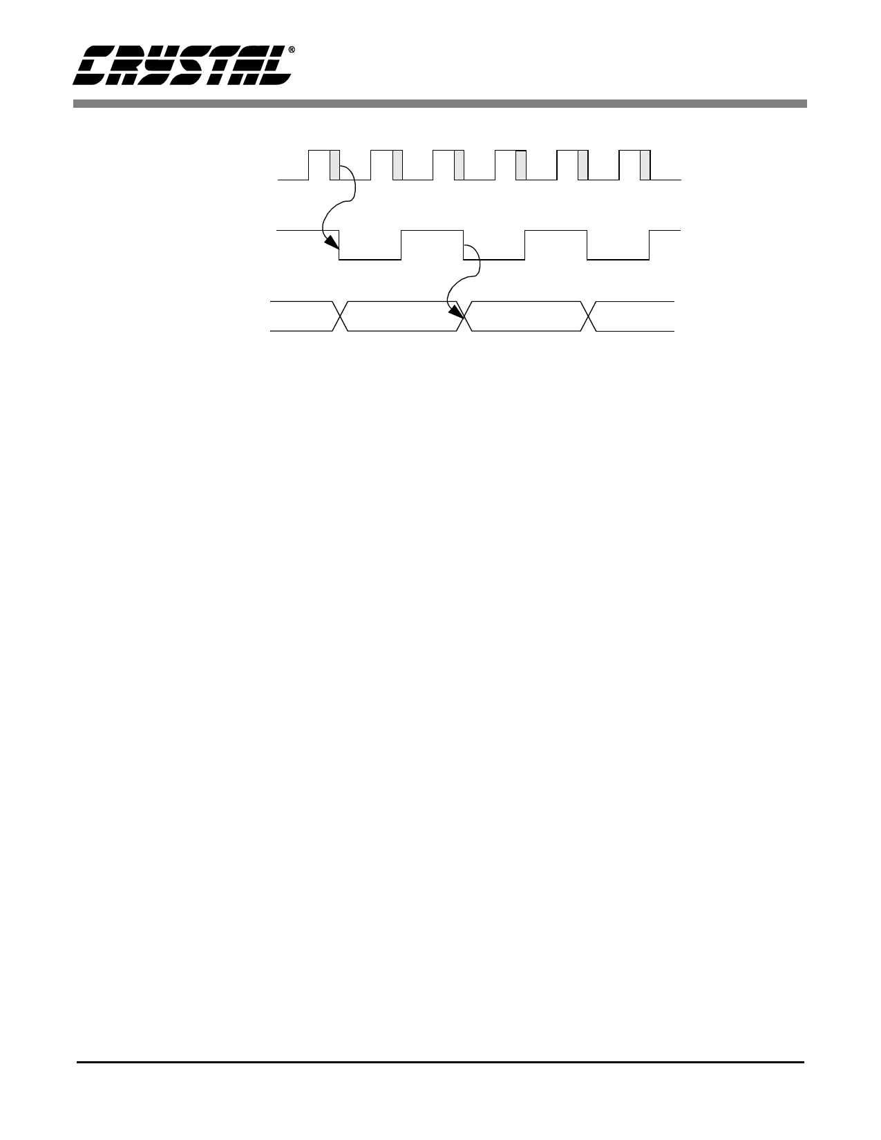
CLK2XO
CLKO
DO[0..9]
Figure 7. CS7615 Output Data and Clocks
CCD Timing Generator
The CCD timing and control signal outputs are dic-
tated by the programmable register settings. This
allows for compatibility with a variety of CCDs.
The HSYNC signal is also output for use in a gen-
lock configuration. The open-drain HCLK can be
used to clock dc-dc voltage converters which are
typically used to generate the CCD imager bias
voltages. The following description explains the
various output signals provided to the vertical driv-
er and CCD as well as the programmable parame-
ters that may be set to control these signals.
HREF* - horizontal reference signal. It stays
high during the active video portion of the line.
HENB* - Horizontal shift register clock enable
signal. Enables H1 and H2 out of analog tim-
ing.
CLAMP* - Black clamp signal provided to the
ADC.
V1X, V2X, V3X, V4X - Vertical register shift
clock. Used both during vertical transfer and
charge read out.
VH1X, VH3X - CCD charge read out pulse.
HCLK - Signal used by the dc - dc converter. In
the normal mode, it is the same as HREF; In
fast mode, it operates at about 16× of the hori-
zontal line frequency and is reset at the begin-
ning of HREF.
HSYNC - Horizontal sync signal.
OFDX - Overflow drain control clock. This
signal sets the electronic shutter speed.
VRST - Vertical field reset signal.
VREF* - Vertical reference signal. It is high
during the active video lines.
*Internal signal on the CS7615 - not a chip output.
Vertical Timing Specifications
The CCD array is read out alternately as odd and
even fields with interlaced horizontal lines. Thus
each field has half the total number of horizontal
rows. Table 1 specifies the programmable vertical
timings which are defined in Figure 8. The timings
vary based on odd or even field, 525 or 625 line
CCD, and the manufacturer.
Horizontal Timing Specifications
Each horizontal row of the CCD is divided into
several regions corresponding to the type of pixels
present. Different CCDs have different numbers of
pixels in each region and the timing signals must
take this into account. The different pixel types in-
clude optical black pixels (front and rear), dummy
pixels, active video pixels, and blank video. The
horizontal timing for the CCD is based on main-
taining a fixed 63.5 µs horizontal line time.
8
DS231PP6
Share Link: 