DFA02 データシートの表示(PDF) - Vishay Semiconductors
部品番号
コンポーネント説明
メーカー
DFA02 Datasheet PDF : 4 Pages
| |||
DF005MA thru DF10MA
Vishay General Semiconductor
New Product
ELECTRICAL CHARACTERISTICS (TA = 25 °C unless otherwise noted)
PARAMETER
TEST
CONDITIONS
SYMBOL
DF005MA DF01MA DF02MA DF04MA DF06MA DF08MA DF10MA
UNIT
Maximum
instantaneous forward
1.0 A
VF
voltage drop per diode
1.1
V
Maximum reverse current
at rated DC blocking
voltage per diode
TA = 25 °C
TA = 125 °C
IR
5.0
500
µA
Typical junction
capacitance per diode
4.0 V, 1 MHz
CJ
25
pF
THERMAL CHARACTERISTICS (TA = 25 °C unless otherwise noted)
PARAMETER
SYMBOL DF005MA DF01MA DF02MA DF04MA DF06MA DF08MA DF10MA UNIT
Typical thermal resistance (1)
Note:
RθJA
RθJL
40
15
°C/W
(1) Thermal resistance from junction to ambient and from junction to lead mounted on P.C.B. with 0.5 x 0.5" (13 x 13 mm) copper pads
ORDERING INFORMATION (Example)
PREFERRED P/N UNIT WEIGHT (g) PREFERRED PACKAGE CODE
DF06MA-E3/45
0.403
45
BASE QUANTITY
50
DELIVERY MODE
Tube
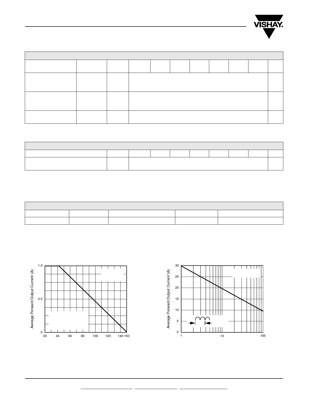
RATINGS AND CHARACTERISTICS CURVES
(TA = 25 °C unless otherwise noted)
1.0
60 Hz
Resistive or
Inductive Load
0.5
P.C.B. Mounted on
0.51 x 0.51" (13 x 13 mm)
Copper Pads with 0.06"
(1.5 mm) Lead Length
0
20
40
60
80 100 120
Ambient Temperature (°C)
140 150
Figure 1. Derating Curve Output Rectified Current
30
TJ = 150 °C
25
Single Sine-Wave
20
15
10
5
1.0 Cycle
0
1
10
100
Number of Cycles at 60 Hz
Figure 2. Maximum Non-Repetitive Peak Forward Surge
Current Per Diode
www.vishay.com
2
For technical questions within your region, please contact one of the following: Document Number: 88572
PDD-Americas@vishay.com, PDD-Asia@vishay.com, PDD-Europe@vishay.com
Revision: 14-Jan-08
Share Link: 