HV301 データシートの表示(PDF) - Supertex Inc
部品番号
コンポーネント説明
メーカー
HV301 Datasheet PDF : 21 Pages
| |||
Design Information, cont’d.
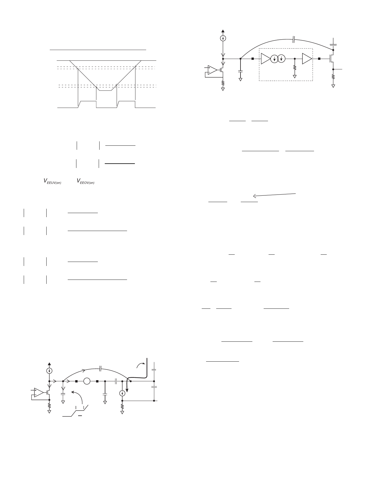
Undervoltage/Overvoltage Operation
GND
UVOFF
UVON
VIN
OVON
OVOFF
Pass ON
Transistor OFF
From the calculated resistor values the OV and UV start up
threshold voltages can be calculated as follows:
UVON
= VUVH
= 1.26 =
VEEUV(on)
×
R2 + R3
R1 + R2 + R3
OVON
= VOVL
= 1.16 =
VEEOV(on)
×
R3
R1 + R2 + R3
Where |VEEUV(on)| and |VEEOV(on)| are Under & Over Voltage Start
Up Threshold points relative to VEE.
Then
VEEUV(on)
= 1.26 ×
R1 + R2 + R3
R2 + R3
VEEUV(on)
= 1.26 ×
487kΩ + 6.81kΩ + 9.76kΩ
6.81kΩ + 9.76kΩ
= 38.29V
And
VEEOV(on)
= 1.16 ×
R1 + R2 + R3
R3
VEEOV(on)
= 1.16 ×
487kΩ + 6.81kΩ + 9.76kΩ
9.76kΩ
= 59.85V
Therefore, the circuit will start when the input supply voltage is
in the range of 38.29V to 59.85V.
Programming Inrush and ICB (Circuit Breaker)
Method 1: Inrush independent of ICB
VSENSE
10V
10µA
7.5µA
2.5µA
5k
7.5µA
C2
–+
0µA
GATE
+K–
RAMP
0µA
10n
Vgs +
–
Cgd
Cgs
dv on Cramp constant
df during limiting so no
current flowing into cap
inrush
Vin
+
Cload=100µF
–
gm(Vgs-Vt)
Rsense=12.5mΩ
(DRAIN)
Cdb
VSENSE
10V
10µA
VSENSE
10µA
Isink
5k
RAMP
terminal
10n=Cramp
HV301/HV311
C2
0.75nF
1 : 2 mirror
Internal Circuitry
48V
Cload
GATE
Termial
Rsense
Vsense
1. Choose circuit breaker trip point eg. 8A as follows
Rsense = 100mV = 100mV = 12.5mΩ
ICB
8
2. Choose inrush level, for example Inrush = 1A
3. Calculate Isink = Inrush *Rsense = 1A ×12.5mΩ = 2.5µA
5kΩ
5kΩ
4. Calculate C2 discharge limit
= 10µA -Isink = 7.5µA (typical) = iC2
4a. Adjust for Auto - retry disable, if used →
Max Vt of a typical
≅ Vtmax e.g. 4V = 1.6µA
R disable
2.5MΩ
power FET
⇒ e.g. iC2 = 10µA -Isink -1.6µA
In this example we assume Auto - retry is enabled so
ignore 1.6µA, ∴ iC2 = 10µA -Isink = 7.5µA
5. Note: i = C dv
dt
iC2
=
C2
×
dv
dt
Inrush
=
Cload
×
dv
dt
Note VIN is fixed and VRAMP is constant during limiting
⇒
dv
dt
across Cload =
dv
dt
across C2
(as they share a
common node and their other terminals are fixed during inrush)
iC2 = Inrush ⇒ Inrush = iC2 × Cload
C2 Cload
C2
by conservation of charge on RAMP Node iC2 = 7.5µA
Inrush =
7.5µA × Cload
C2
⇒ C2
=
7.5µA × Cload
Inrush
= 7.5µA ×100nF = 750pF = 0.75nF
1A
Note that RAMP is protected by AC divider and Gate
is clamped internally.
6
Share Link: 