HV311 データシートの表示(PDF) - Supertex Inc
部品番号
コンポーネント説明
メーカー
HV311 Datasheet PDF : 21 Pages
| |||
Design Information, cont’d.
These equations assume that the load is purely capacitive and
the following definitions apply.
CRAMP is the external capacitor connected to the RAMP pin.
IRAMP is the output current from the RAMP pin, nominally
10µA, when the voltage drop on RSENSE resistor is zero.
VINT is the internally regulated supply voltage and can range
from 8.5V to 12V.
VGS(th) is the gate threshold voltage of the external pass
transistor and may be obtained from its datasheet.
VGS(limit) is the external pass transistor gate-source voltage
required to obtain the limit current. It is dependent on the
pass transistor’s characteristics and may be obtained from
the transfer characteristics on the transistor datasheet.
gfs is the transconductance of the external pass transistor
and may be obtained from its datasheet.
RFB is the internal feedback resistor and is nominally 5kΩ.
ILIMIT is the load current when the voltage drop on the RSENSE
resistor is 50mV.
These equations may be used to calculate the minimum value of
CRAMP for the most critical system performance characteristics.
For maximum contact bounce duration protection choose a
value for tPOR and use the following equation:
CRAMP
=
tPOR × IRAMP
2.4 + VGS(th)
If control of PWRGD active delay is the critical system param-
eter, then choose a value for tPWRGD and use the following
equation:
CRAMP
=
tPWRGD × IRAMP
VINT − VGS(limit) − 1.2
HV301/HV311
Start up Overload Protection
Start up must be achieved within a nominal 100ms as indicated
by the PWRGD pin transition to the active state or the circuit will
reset and an automatic restart will initiate. If there is an output
overload or short circuit during start up, the circuit will be in
current limit for the 100ms time limit (in servo mode). In feedback
capacitor mode the circuit breaker will shutdown the pass FET
before 100ms.
Circuit Breaker
The circuit breaker will trip in less than 5µs when the voltage on
the SENSE pin reaches a nominal 100mV. A resistor in series
with the SENSE pin and a capacitor connected between the
SENSE and VEE pins may be added to delay the rate of voltage
rise on the SENSE pin, thus permitting a current overshoot and
delaying Circuit Breaker activation.
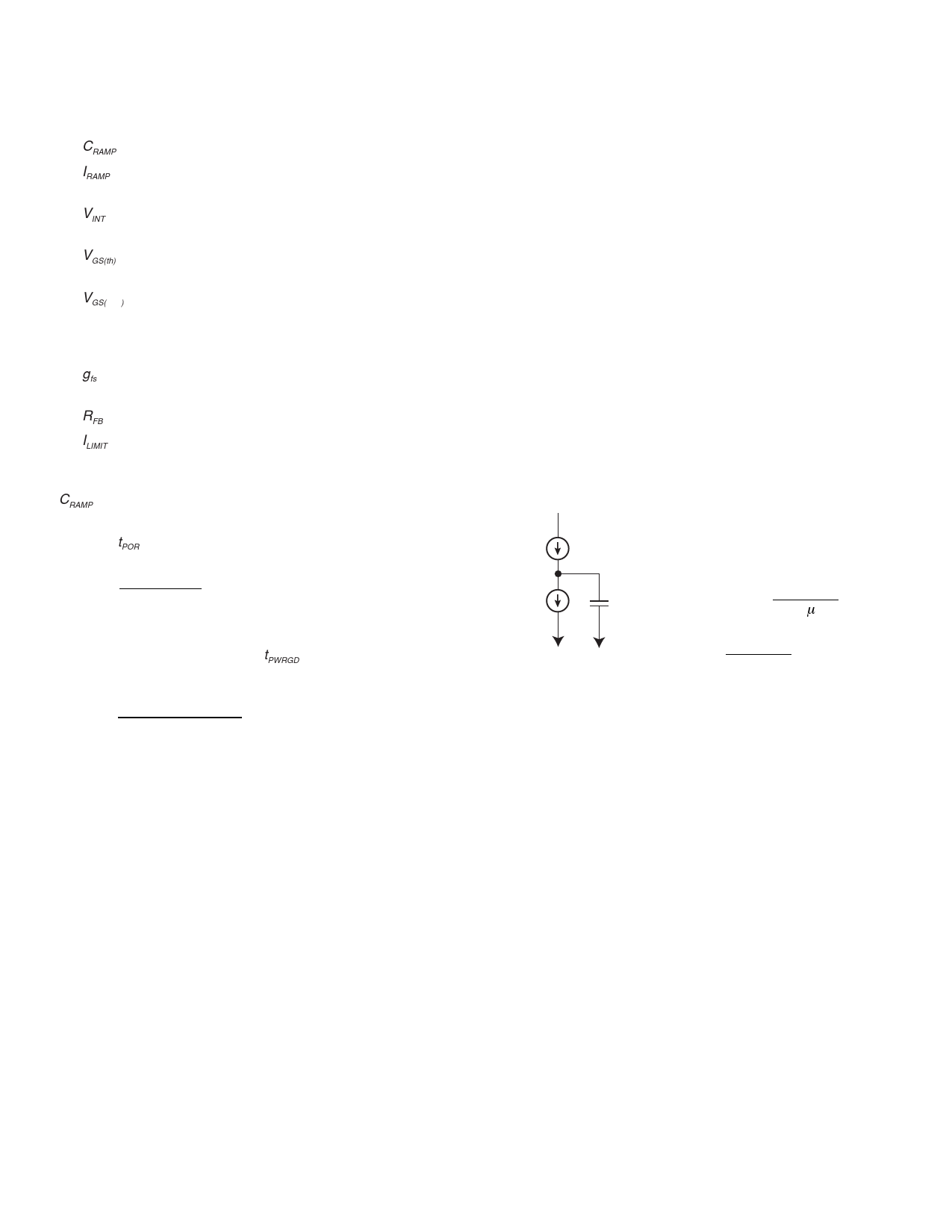
Automatic Restart
The automatic restart delay time is directly proportional to the
capacitance at the RAMP pin. Automatic restart sequence is
activated whenever the 100ms timeout is reached during start up
or the circuit breaker is tripped.
Auto-retry can be approximated as a
555-timer with 2.5µA charge up and
2.5µA
charge down currents through 8V, to
a count of 256. Therefore,
2.5µA
Cramp
TAUTORETRY
=
2
× 8 × 256
2.5µA
×
Cramp
e.g. 2 × 8 × 256 × Ion = 16.4s
2.5µA
Due to the 2.5µA max charge current a resistor which draws
more than 2.5µA below 8V will disable the autoretry. Try to
keep this resistor as big as possible, e.g. 2.5MΩ, for most
MOSFETs with max Vt of 4V this will vary the 10µA Ramp
current source by only 4/2.5MΩ=1.6µA.
8
Share Link: 