DM74123 データシートの表示(PDF) - Fairchild Semiconductor
部品番号
コンポーネント説明
メーカー
DM74123 Datasheet PDF : 5 Pages
| |||
August 1986
Revised July 2001
DM74123
Dual Retriggerable One-Shot
with Clear and Complementary Outputs
General Description
The DM74123 is a dual retriggerable monostable multi-
vibrator capable of generating output pulses from a few
nano-seconds to extremely long duration up to 100% duty
cycle. Each device has three inputs permitting the choice of
either leading-edge or trailing edge triggering. Pin (A) is an
active-LOW transition trigger input and pin (B) is an active-
HIGH transition trigger input. A LOW at the clear (CLR)
input terminates the output pulse: which also inhibits trig-
gering. An internal connection from CLR to the input gate
makes it possible to trigger the circuit by a positive-going
signal on CLR as shown in the Truth Table.
To obtain the best and trouble free operation from this
device please read the Operating Rules as well as the
One–Shot Application Notes carefully and observe recom-
mendations.
Features
s DC triggered from active-HIGH transition or active-LOW
transition inputs
s Retriggerable to 100% duty cycle
s Direct reset terminates output pulse
s Compensated for VCC and temperature variations
s DTL, TTL compatible
s Input clamp diodes
Ordering Code:
Order Number Package Number
Package Description
DM74123N
N16E
16-Lead Plastic Dual-In-Line Package (PDIP), JEDEC MS-001, 0.300" Wide
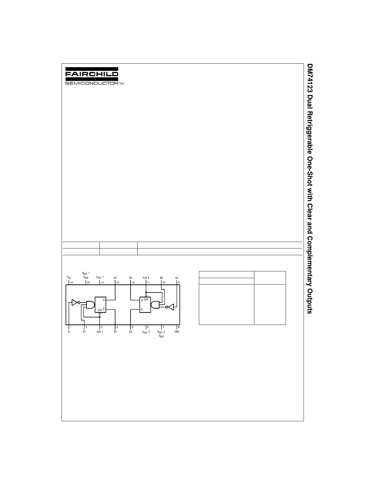
Connection Diagram
Functional Description
The basic output pulse width is determined by selection of
an external resistor (RX) and capacitor (CX). Once trig-
gered, the basic pulse width may be extended by retrigger-
ing the gated active-LOW transition or active-HIGH
transition inputs or be reduced by use of the active-LOW
Triggering Truth Table
Inputs
A
B
X
H
L
X
L
H
L
H
H = HIGH Voltage Level
L = LOW Voltage Level
X = Immaterial
CLR
L
X
H
X
H
Response
No Trigger
No Trigger
Trigger
No Trigger
Trigger
Trigger
transition clear input. Retriggering to 100% duty cycle is
possible by application of an input pulse train whose cycle
time is shorter than the output cycle time such that a con-
tinuous “HIGH” logic state is maintained at the “Q” output.
© 2001 Fairchild Semiconductor Corporation DS006539
www.fairchildsemi.com
Share Link: 