S1T8528 データシートの表示(PDF) - Samsung
部品番号
コンポーネント説明
メーカー
S1T8528 Datasheet PDF : 35 Pages
| |||
ENHANCED-1 CHIP CT0 RF IC
S1T8528
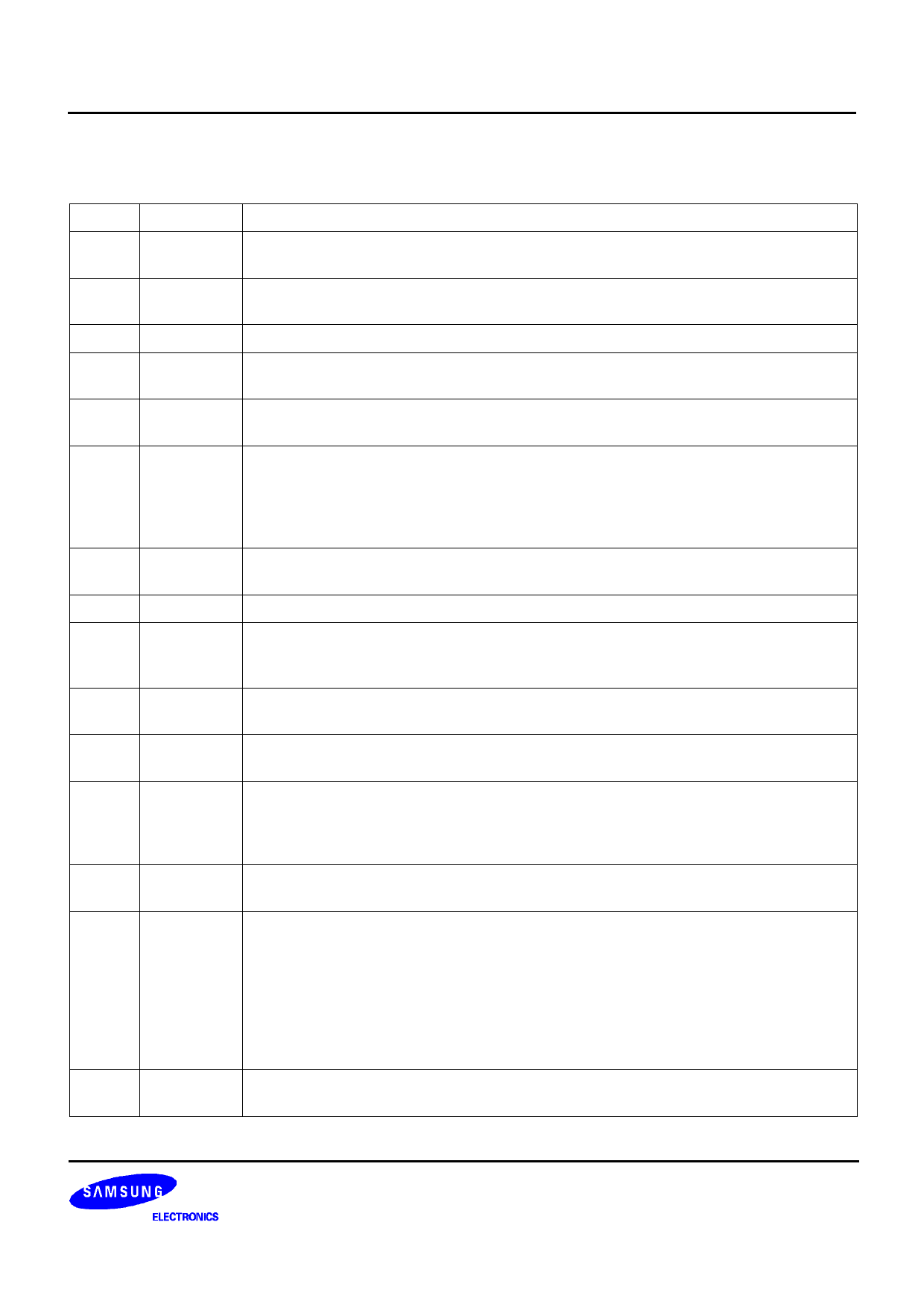
PIN DESCRIPTION (Continued)
Pin No Symbol
18
SAO 1
19
SAI
20
EO
21
ERC
22
EPI
23
ALC
24
VREF(COMP)
25
RSSI
26
DSCO
27
DSCI
28
RAO
29
QCI
30
GNDRX
31
LD
32
LI
33
VCC(RX)
Description
Output terminal of Speaker amp 1.
DC voltage level is Vcc/ 2.
Speaker Amp 1 input terminal.
Between this terminal and Expander output terminal, apply DC coupled capacitor.
Output terminal of Expander
Converts waveform from the full wave rectifier to DC element at the rectifier block of
Expander. ( RC = 33 msec at C = 3.3uF )
Pre-amp inverting input terminal of Expander.
Adjusts the negative feedback loop gain. ( in application, gain is 5 )
Reference current input terminal of Automatic Level Control ( ALC); Adjusts THD of
compressor output voltage to less than 3% or limits the frequency deviation of TX if the
input is higher than a certain level. The ALC circuit may be turned off depending on the
ALC reference current or the magnitude of output voltage may be limited if it is higher
than a certain level.
Reference voltage ( VREF= 1/2 VCC ). Supplies a regulator voltage to the Compressor
and Expander of COMPANDER.
Received Signal Strength Indicator terminal ( Analog type )
Output terminal of Data Slicing comparator.
Separates Frequency Shift Keying ( FSK ) serial data and executes data shaping and
limiting.
Input terminal of Data slicing comparator.
Non-inverting type with the negative input terminal biased to 1/2 Vcc.
Recovered Audio Output terminal. Voice signals detected by the Quadrature Detector
are amplified and then output through this terminal.
Quadrature coil input terminal.
The 455kHz oscillator circuit is an Lp = 680uH, Cp = 180pF valued LC tank circuit.
Voice signals are detected by mixture of 455kHz ( by phase difference ) which is
converted from mixer 2.
Ground .
Ground for Receiver.
Limiter input and decoupling terminal.
Limiter block removes amplitude modulation elements caused by fading or FM signal
noise. Limiting IF stage makes the second intermediate frequency amplify and limit.
The input impedance of the limiting IF amplifier is set to 1.5kΩ.
While FM waves are transmitted with constant magnitude, their magnitudes are slightly
modulated due to reflection from obstacles, fading phenomenon, noise wave and
mixing with AM wave elements before entering the receiver’s antenna.
The limiter makes amplitude uniform by removing these AM wave elements.
Supply voltage.
Supplies power to the Receiver.
5
Share Link: 