TC07VUA データシートの表示(PDF) - TelCom Semiconductor Inc => Microchip
部品番号
コンポーネント説明
メーカー
TC07VUA
TelCom Semiconductor Inc => Microchip

TC07VUA Datasheet PDF : 3 Pages
| |||
TC07
3V LOGIC OUTPUT TEMPERATURE
SENSOR WITH PROGRAMMABLE
HYSTERESIS
ABSOLUTE MAXIMUM RATINGS*
Supply Voltage ..............................................................7V
Input Voltage Any Input ...... (GND – 0.3V) to (VDD + 0.3V)
Operating Temperature ......................... – 40°C to +125°C
Maximum Chip Temperature ................................. +150°C
Storage Temperature ............................ – 65°C to +150°C
Lead Temperature (Soldering, 10 sec) ................. +300°C
* Stresses above those listed under "Absolute Maximum Ratings" may
cause permanent damage to the device. These are stress ratings only and
functional operation of the device at these or any other conditions above
those indicated in the operation sections of the specifications is not implied.
Exposure to absolute maximum rating conditions for extended periods may
affect device reliability.
ELECTRICAL CHARACTERISTICS: TA = Over Operational Temperature Range, unless otherwise specified.
Symbol
VDD
IDD
VOH
VOL
H
TSET
HSET
Parameter
Supply Voltage Range
Supply Current
Output Voltage (High)
Output Voltage (Low)
Minimum Hysteresis
Absolute Accuracy
Absolute Accuracy
Conditions
2.7V < VCC < 5.5V
IOUT = 500µA
IOUT = 1mA
HSET < TSET
T = Programmed Temperature
T = Programmed Temperature
Min
2.7
—
0.8 x VDD
—
–5
T–3
T–5
Typ
—
130
—
—
—
T±1
T±1
Max
5.5
300
—
0.25 x VDD
—
T+3
T+5
Unit
V
µA
V
V
°C
°C
°C
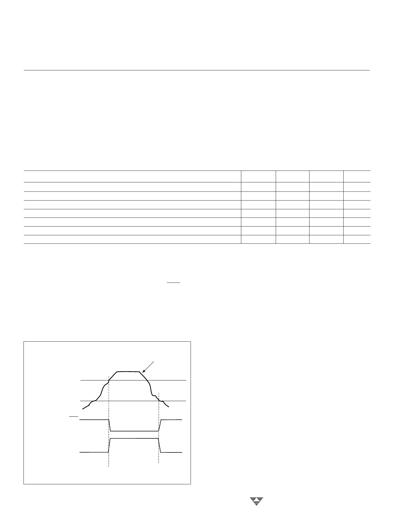
DETAILED DESCRIPTION
The TC07 programs with resistors connected from the
TSET and HSET inputs to VDD. Output pins OUT and OUT are
driven active when temperature exceeds the setting deter-
mined by the programming resistor on TSET. The outputs are
maintained (latched) in their active states until temperature
drops below the setting determined by the programming
resistor on HSET (Figure 1).
APPLICATIONS
Trip Point Programming
The resistor values required to achieve the desired
trip-point temperatures on TSET and HSET are calculated
using the formula below:
RTRIP = 0.6 x T 2.13
TEMPERATURE SET BY
RESISTOR ON TSET
HYSTERESIS SET BY
RESISTOR ON HSET
TEMPERATURE
Where:
RTRIP
T
= Programming resistor value in Ohms
= Desired trip point temperature in degrees
Kelvin.
For example, to program the TC07 outputs to go active
at 50°C and inactive at 30°C, the TSET and HSET program-
ming resistors are calculated as follows:
OUT
TSET = 0.6 x ((50 + 273.15)2.13) = 132.8kΩ
HSET = 0.6 x ((30 + 273.15)2.13) = 115.9kΩ
OUT
2-12
Figure 1. TC07 Output Waveforms
Resistance values for TSET and HSET can be approxi-
mated using Figure 2. Care must be taken to ensure the
HSET programming resistor is a smaller value than the TSET
programming resistor. The temperature programmed on
HSET must be at least 5°C lower than the temperature value
programmed by TSET. That is: HSET ≤ TSET – 5°C.
TELCOM SEMICONDUCTOR, INC.
Share Link: