PDM31096SA10SO データシートの表示(PDF) - Paradigm Technology
部品番号
コンポーネント説明
メーカー
PDM31096SA10SO Datasheet PDF : 8 Pages
| |||
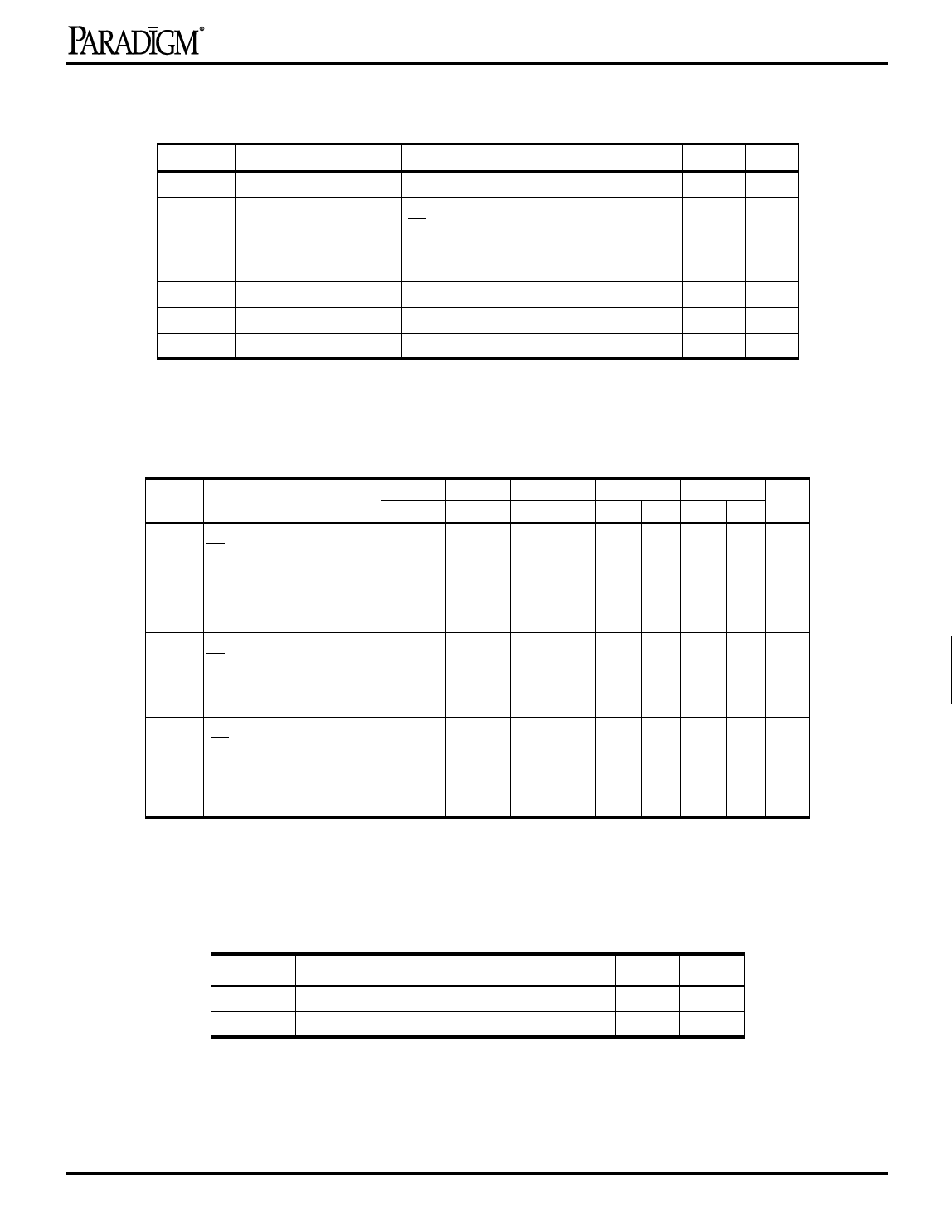
PRELIMINARY
PDM31096
DC Electrical Characteristics (VCC = 3.3V ± 0.3V)
Symbol Parameter
Test Conditions
ILI
Input Leakage Current
VCC = Max., VIN = VSS to VCC
ILO
Output Leakage Current VCC = Max.,
CE = VIH
VOUT = VSS to VCC
VIL
Input Low Voltage
VIH
Input High Voltage
VOL
Output Low Voltage
IOL = 8 mA, VCC = Min.
VOH
Output High Voltage
IOH = –4 mA, VCC = Min.
NOTE:1.VIL(min) = –3.0V for pulse width less than 20 ns
Min.
–5
–5
Max. Unit
5
µA
5
µA
–0.3(1)
0.8
V
2.2 Vcc+0.3 V
—
0.4
V
2.4
—
V
Power Supply Characteristics
Symbol Parameter
ICC Operating Current
CE = VIL
-8
Com’l.
230
-10
-12
-15
-20
Com’l. Com’l Ind. Com’l Ind. Com’l Ind. Unit
215 200 220 160 200 120 160 mA
f = fMAX = 1/tRC
VCC = Max.
IOUT = 0 mA
ISB Standby Current
CE = VIH
50
45
f = fMAX = 1/tRC
VCC = Max.
ISB1 Full Standby Current
CE ≥ VCC – 0.2V
10
10
f=0
VCC = Max.,
VIN ≥ VCC – 0.2V or ≤ 0.2V
NOTES: All values are maximum guaranteed values.
40 45 35 40 30 35 mA
10 15 10 15 10 15 mA
Capacitance(1) (TA = +25°C, f = 1.0 MHz)
Symbol
Parameter
Max.
Unit
CIN
COUT
Input Capacitance
Output Capacitance
8
pF
8
pF
NOTE: 1. This parameter is determined by device characterization but is not production tested.
1
2
3
4
5
6
7
8
9
10
11
12
Rev. 2.4 - 5/27/98
3
Share Link: 