QL3006 データシートの表示(PDF) - QuickLogic Corporation
部品番号
コンポーネント説明
メーカー
QL3006
QuickLogic Corporation

QL3006 Datasheet PDF : 49 Pages
| |||
pASIC 3 FPGA Family Data Sheet Rev. D
Symbol
tACK
tGCKP
tGCKB
Parameter
Array Clock Delay
Global Clock Pin Delay
Global Clock Buffer Delay
Table 5: Clock Cells
Propagation Delays (ns) Loads per Half Column a
1
2
3
4
8
10
11
1.2
1.2
1.3
1.3
1.5
1.6
1.7
0.7
0.7
0.7
0.7
0.7
0.7
0.7
0.8
0.8
0.9
0.9
1.1
1.2
1.3
a. The array distributed networks consist of 40 half columns and the global distributed networks consist of 44 half columns, each driven
by an independent buffer. The number of half columns used does not affect clock buffer delay. The array clock has up to eight loads
per half column. The global clock has up to 11 loads per half column.
Table 6: Input-Only I/O Cells
Symbol
Parameter
Propagation Delays (ns) Fanout a
1
2
3
4
8
10
tI/O
tISU
tIH
tlOCLK
tlORST
tlESU
tlEH
Input Delay (bidirectional pad)
Input Register Set-Up Time
Input Register Hold Time
Input Register Clock To Q
Input Register Reset Delay
Input Register clock Enable Set-Up Time
Input Register Clock Enable Hold Time
1.3 1.6 1.8 2.1 3.1 3.6
3.1 3.1 3.1 3.1 3.1 3.1
0.0 0.0 0.0 0.0 0.0 0.0
0.7 1.0 1.2 1.5 2.5 3.0
0.6 0.9 1.1 1.4 2.4 2.9
2.3 2.3 2.3 2.3 2.3 2.3
0.0 0.0 0.0 0.0 0.0 0.0
a. Stated timing for worst case Propagation Delay over process variation at VCC = 3.3 V and TA = 25°C. Multiply by the appropriate
Delay Factor, K, for speed grade, voltage, and temperature settings as specified in Table 9.
Table 7: Output-Only I/O Cells
Symbol
Parameter
Propagation Delays (ns) Output Load Capacitance (pF)
30
50
75
100
150
tOUTLH
Output Delay Low to High
2.1
2.5
3.1
3.6
4.7
tOUTHL
Output Delay High to Low
2.2
2.6
3.2
3.7
4.8
tPZH
Output Delay Tri-state to High
1.2
1.7
2.2
2.8
3.9
tPZL
Output Delay Tri-state to Low
1.6
2.0
2.6
3.1
4.2
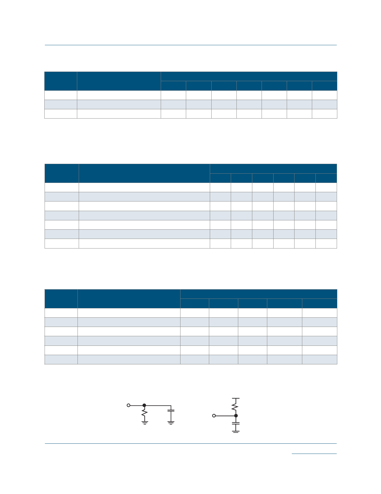
tPHZ
Output Delay High to Tri-State a
2.0
-
-
-
-
tPLZ
Output Delay Low to Tri-State
1.2
-
-
-
-
a. The loads presented in Figure 2 are used for tPXZ:
Figure 2: Loads used for tPXZ
1ΚΩ
tPHZ
5 pF
1ΚΩ
tPLZ
5 pF
© 2005 QuickLogic Corporation
www.quicklogic.com
•
•••
••
5
Share Link: