FS6377-01G-XTP データシートの表示(PDF) - ON Semiconductor
部品番号
コンポーネント説明
メーカー
FS6377-01G-XTP Datasheet PDF : 24 Pages
| |||
FS6377
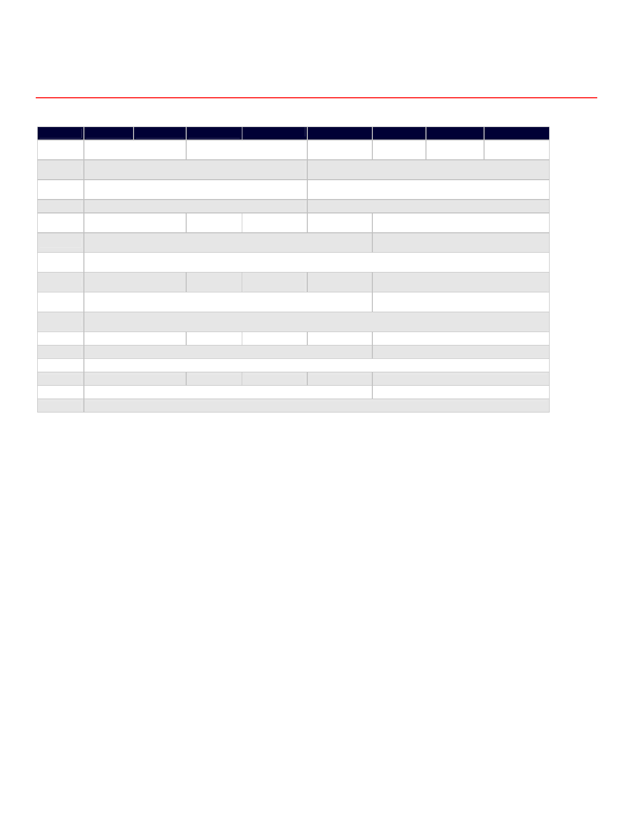
6.0 Programming Information
Table 3: Register Map
Address
BIT 7
BIT 6
BIT 5
BIT 4
BIT 3
BIT 2
BIT 1
BIT 0
Byte 15
Byte 14
Byte 13
MUX_D2[1:0]
MUX_C2[1:0]
(selected via SEL_CD = 1 (selected via SEL_CD = 1)
POST_D2[3:0]
(selected via SEL_CD = 1)
POST_D1[3:0]
(selected via SEL_CD = 0)
PDPOST_D
PDPOST_C PDPOST_B PDPOST_A
POST_C2[3:0]
(selected via SEL_CD = 1)
POST_C1[3:0]
(selected via SEL_CD = 0)
Byte 12
POST_B[3:0]
POST_A[3:0]
Byte 11
Byte 10
Byte 9
Byte 8
Byte 7
Byte 6
MUX_D1[1:0]
(selected via SEL_CD = 0)
Reserved (0)
LFTC_C2
(SEL_CD = 1)
CP_C2
(SEL_CD = 1)
FBKDIV_C2[7:3] M-Counter
(selected via SEL_CD pin = 1)
REFDIV_C2[7:0]
(selected via SEL_CD pin = 1)
MUX_C1[1:0]
(selected via SEL_CD = 0)
PDPLL_C
LFTC_C1
CP_C1
(SEL_CD = 0) (SEL_CD = 0)
FBKDIV_C1[7:3] M-Counter
(selected via SEL_CD = 0)
REFDIV_C1[7:0]
(selected via SEL_CD = 0)
FBKDIV_D2[10:8] M-Counter
(selected via SEL_CD pin = 1)
FBKDIV_C2[2:0] A-Counter
(selected via SEL_CD pin = 1)
FBKDIV_c1[10:8] M-Counter
(selected via SEL_CD = 0)
FBKDIV_C1[2:0] A-Counter
(selected via SEL_CD = 1)
Byte 5
MUX_B[1:0]
PDPLL_B
LFTC_B
CP_B
FBKDIV_B[10:8] M-Counter
Byte 4
FBKDIV_B[7:3] M-Counter
FBKDIV_B[2:0] A-Counter
Byte 3
REFDIV_B[7:0]
Byte 2
MUX_A[1:0]
PDPLL_A
LFTC_A
CP_A
FBKDIV_A[10:8] M-Counter
Byte 1
FBKDIV_A[7:3] M-Counter
FBKDIV_A[2:0] A-Counter
Byte 0
REFDIV_A[7:0]
Note: All register bits are cleared to zero on power-up.
6.1 Control Bit Assignment
If any PLL control bit is altered during device operation, including those bits controlling the reference and feedback dividers, the output
frequency will slew smoothly (in a glitch-free manner) to the new frequency. The slew rate is related to the programmed loop filter time
constant.
However, any programming changes to any mux or post divider control bits will cause a glitch on an operating clock output.
Rev. 4 | Page 10 of 24 | www.onsemi.com
Share Link: 