HT1647 データシートの表示(PDF) - Holtek Semiconductor
部品番号
コンポーネント説明
メーカー
HT1647 Datasheet PDF : 17 Pages
| |||
HT1647
Time Base and Watchdog Timer - WDT
The time base generator and WDT share the same
counter which is divided by 256. The IRQ clock can be pro-
grammed as 1Hz, 2Hz, ...., 128Hz output. TIMER
DIS/EN/CLR, WDT DIS/EN/CLR and IRQ EN/DIS are in-
dependent from each other. Once the WDT time-out oc-
curs, the IRQ pin will remain at a logic low level until the
CLR WDT or the IRQ DIS command is issued.
If an external clock is selected as the system frequency
source, the SYS DIS command turns out invalid and the
power down mode fails to be carried out until the exter-
nal clock source is removed.
Buzzer Tone Output
A simple tone generator is implemented in the HT1647.
The tone generator can output a pair of differential driv-
ing signals on the BZ and BZ which are used to generate
a single tone.
By executing the TONE 4K and TONE 2K commands
there are two tone frequency outputs selectable that can
turn on the tone output. The TONE 4K and TONE 2K
commands set the tone frequency to 4kHz and 2kHz, re-
spectively. The tone output can be turned off by invoking
the TONE OFF command. The tone outputs, namely BZ
and BZ, are a pair of differential driving outputs used to
drive a piezo buzzer. Once the system is disabled or the
tone output is inhibited, the BZ and the BZ outputs will
remain at low level.
Command Format
The HT1647 can be configured by software setting.
There are two mode commands to configure the
HT1647 resource and to transfer the LCD display data.
The configuration mode of the HT1647 is called com-
mand mode, and its command mode ID is 100. The
command mode consists of a system configuration
command, a system frequency selection command, an
LCD configuration command, a tone frequency selec-
tion command, a bias current selection command, a
gray scale level selection command, a timer/WDT set-
ting command, and an operating command. The data
mode, on the other hand, includes READ, WRITE, and
READ-MODIFY-WRITE operations.
The following are the data mode ID and the command
mode ID:
Operation
READ
WRITE
READ-MODIFY-WRITE
COMMAND
Mode
ID
Data
110
Data
101
Data
101
Command 100
If successive commands have been issued, the com-
mand mode ID can be omitted. While the system is op-
erating in the non-successive command or the
non-successive address data mode, the CS pin should
be set to ²1² and the previous operation mode will also
be reset. The CS pin returns to ²0², so a new operation
mode ID should be issued first.
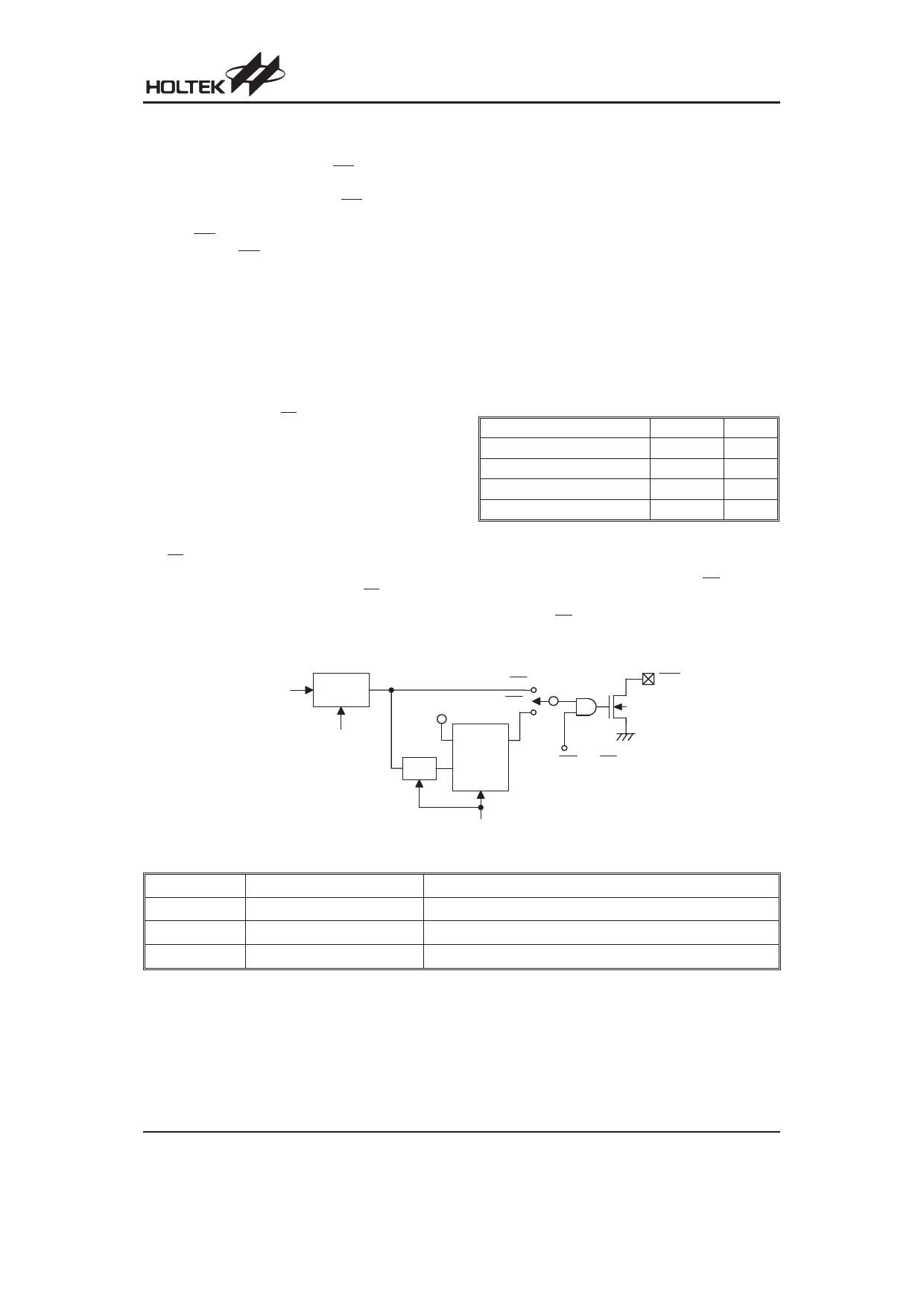
T im e B a s e
C lo c k S o u r c e
/2 5 6
T IM E R E N /D IS
IR Q
V D D W D T E N /D IS
C L R T im e r
D
Q
W DT
/4
CK
R
IR Q E N /D IS
C LR W D T
Time Base and WDT Configurations
Name
TONE OFF
TONE 4K
TONE 2K
Command Code
X100-0000-1000-XXXX
X100-0001-0000-XXXX
X100-0001-0001-XXXX
Function
Turn-off tone output
Turn-on tone output, tone frequency is 4kHz
Turn-on tone output, tone frequency is 2kHz
Buzzer Tone Output Command Code
Rev. 1.30
10
November 10, 2005
Share Link: 