HT1647 データシートの表示(PDF) - Holtek Semiconductor
部品番号
コンポーネント説明
メーカー
HT1647 Datasheet PDF : 17 Pages
| |||
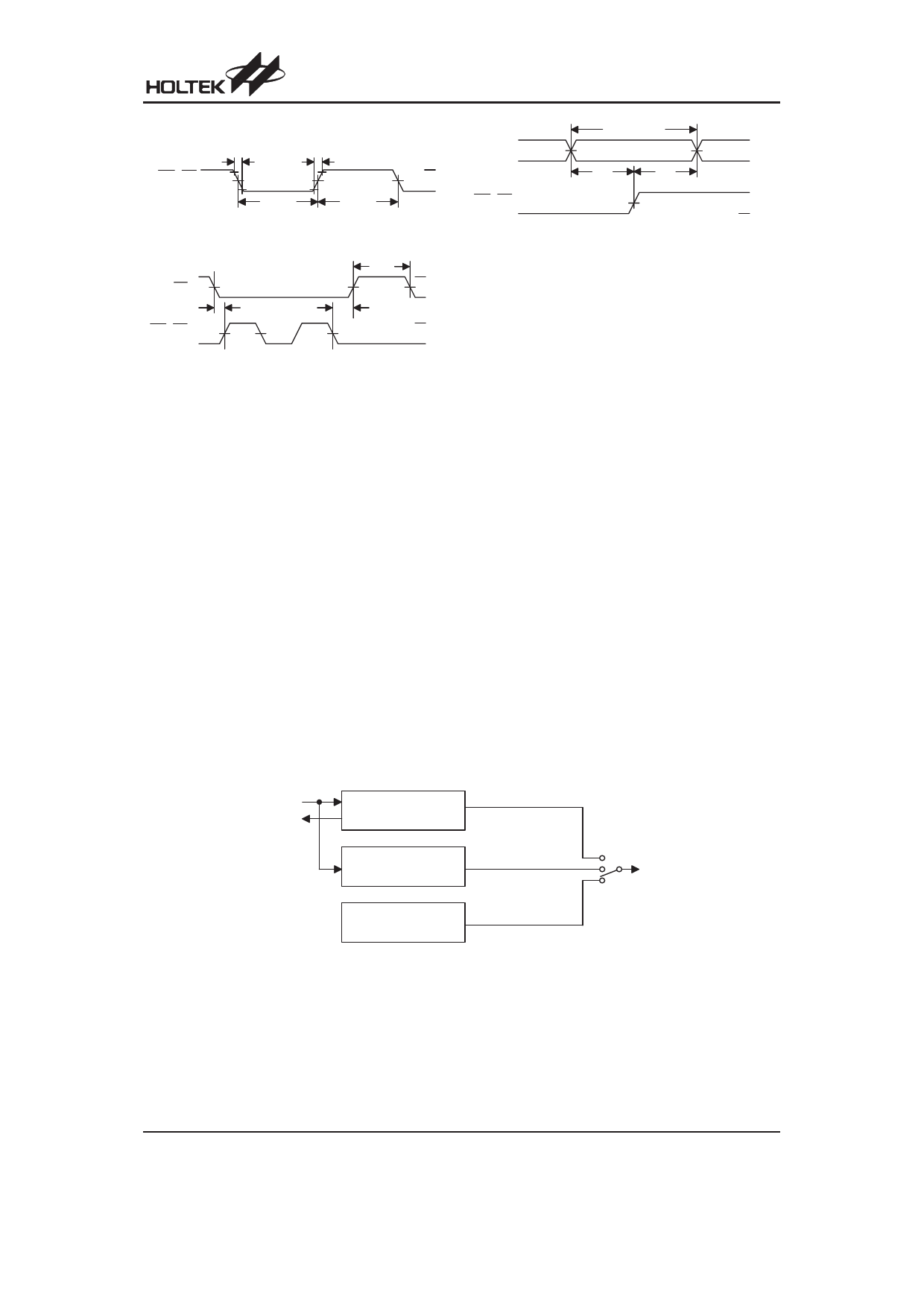
W R ,R D 90%
C lo c k
50%
10%
tf
tr
tC L K
tC L K
Figure 1
CS
W R ,R D
C lo c k
50%
tsu 1
tC S
th 1
50%
F IR S T
C lo c k
LA S T
C lo c k
Figure 3
DB
V DD
GND
W R ,R D
C lo c k
V DD
GND
V DD
GND
V A L ID D A T A
50%
ts u
th
50%
Figure 2
HT1647
V DD
GND
GND
Functional Description
System Oscillator
The HT1647 system clock is used to generate the time
base/Watchdog Timer (WDT) clock frequency, LCD
driving clock, and tone frequency. The clock source
may be from an on-chip RC oscillator (32kHz), a crystal
oscillator (32.768kHz), or an external 32kHz clock by
the S/W setting. The configuration of the system oscilla-
tor is as shown. After the SYS DIS command is exe-
cuted, the system clock will stop and the LCD bias
generator will turn off. That command is available only
for the on-chip RC oscillator or for the crystal oscillator.
Once the system clock stops, the LCD display will be-
come blank, and the time base/WDT loses its function
as well.
The LCD OFF command is used to turn the LCD bias
generator off. After the LCD bias generator switches off
by issuing the LCD OFF command, using the SYS DIS
command reduces power consumption, thus serving as
a system power down command. But if the external
clock source is chosen as the system clock, using the
SYS DIS command can neither turn the oscillator off nor
carry out the power down mode. The crystal oscillator
option can be applied to connect an external frequency
source of 32kHz to the OSCI pin. In this case, the sys-
tem fails to enter the power down mode, similar to the
case in the external 32kHz clock source operation. At
the initial system power on, the HT1647 is at the SYS
DIS state.
Display Memory - RAM Structure
The static display RAM is organized into 512´4 bits and
stores the display data. The contents of the RAM are di-
rectly mapped to the contents of the LCD driver. Data in
the RAM can be accessed by the READ, WRITE and
READ-MODIFY-WRITE commands. The following is a
mapping from the RAM to the LCD patterns.
O SCI
O SCO
C r y s ta l O s c illa to r
32768H z
E x te r n a l C lo c k S o u r c e
32kH z
O n - c h ip R C O s c illa to r
32kH z
System Oscillator Configuration
S y s te m
C lo c k
Rev. 1.30
7
November 10, 2005
Share Link: 