SAA1502ATS データシートの表示(PDF) - Philips Electronics
部品番号
コンポーネント説明
メーカー
SAA1502ATS Datasheet PDF : 20 Pages
| |||
Philips Semiconductors
Safety IC for Li-ion
Preliminary specification
SAA1502ATS
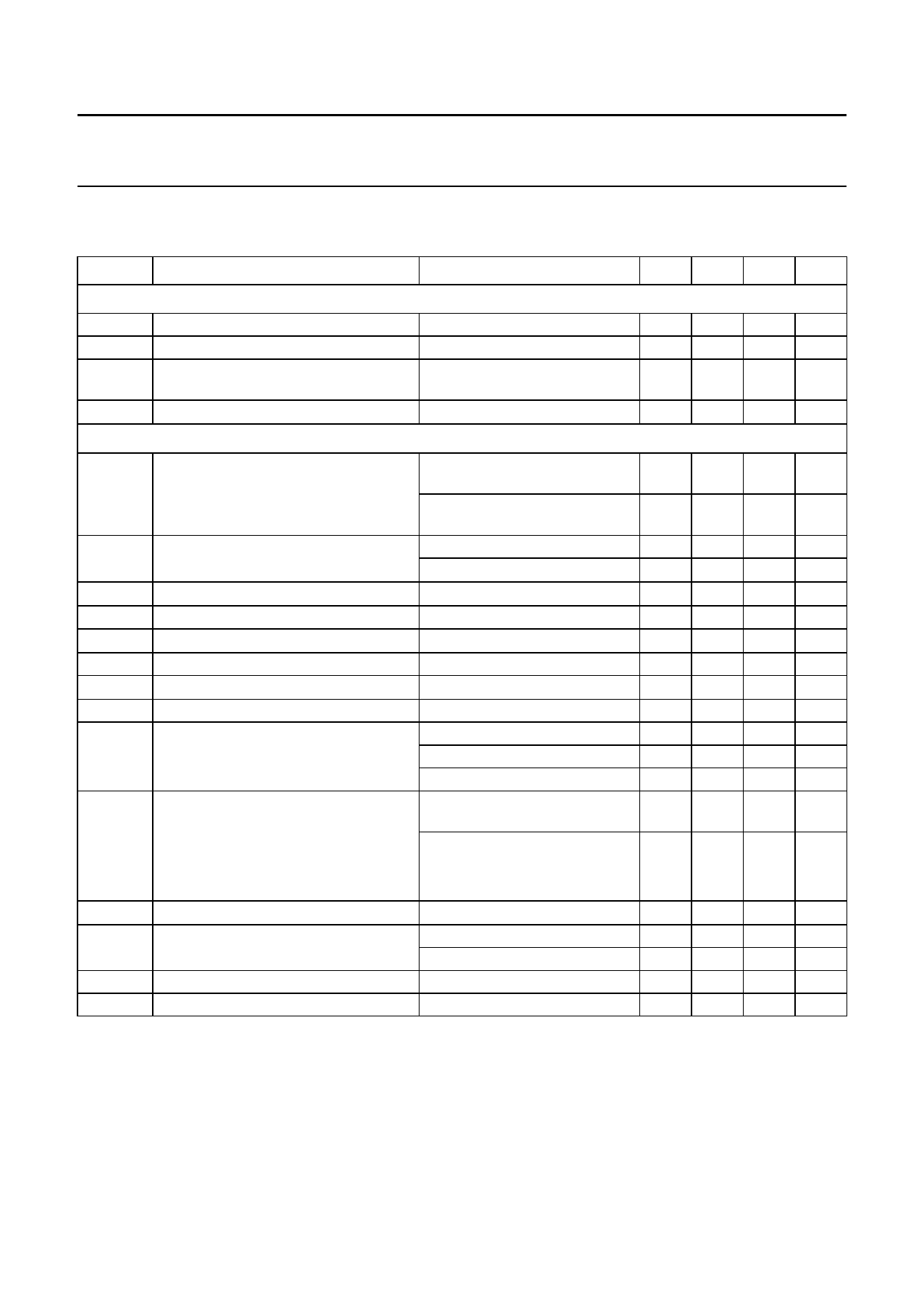
CHARACTERISTICS
Tj = 25 °C; all voltages with respect to VSS2; positive currents flow into the IC.
SYMBOL
PARAMETER
CONDITIONS
Supply behaviour
VCC
positive battery sense input voltage
ICC
supply current
Iq
quiescent current
VCC−VVM minimum charge voltage
Voltage detection
Vec(det) excess charge detection voltage
tec(det)
excess charge delay time Vec(det)
Vec(rel) excess charge release voltage
tec(rel)
excess charge delay time Vec(rel)
Ved(det) excess discharge detection voltage
ted(det)
excess discharge delay time Ved(det)
Ved(rel) excess discharge release voltage
ted(rel)
excess discharge delay time Ved(rel)
IVSS−VM (dis)charge current detection
VVM
negative sense input voltage
VCC−VVM charge present detection voltage
VCC
positive battery sense input voltage
td(on)
td(off)
switch-on delay time SW1/SW2
switch-off delay time SW1/SW2
VCC = 4.0 V; −13.5 V ≤ VVM ≤ 0
Power-down/reset mode
(VCC = 2.0 V)
at zero charge
measured at terminals of the
battery and Tj = 25 °C
measured at terminals of the
battery and Tj = −5 to +55 °C
Cext not connected
Cext = 33 nF (±10%)
charge inhibit state
discharge enable state
discharge inhibit state
discharge inhibit state;
no charge current
current protection mode
no load detection
no charger detection
Power-down mode
start of reset mode
excess of reset mode
VCC = 4.0 V
VCC = 4.0 V
MIN. TYP. MAX. UNIT
0
−
4.5 V
4.0 7.0 10 µA
0.03 0.1 0.3 µA
1.8 2.4 3.0 V
4.15 4.18 4.20 V
4.145 4.18 4.21 V
20 40 60 ms
0.5 1.25 2
s
3.82 3.95 4.08 V
25 50 75 ms
2.2 2.3 2.4 V
20 40 60 ms
3.3 3.6 3.9 V
25 50 75 ms
0.05 1.5 37.5 mA
150 280 475 mA
0.05 1.5 37.5 mA
−7 −12 −20 mV
70 90 120 mV
−7 −12 −20 mV
2.4 3.0 3.6 V
1.7 1.9 2.1 V
2.05 2.25 2.45 V
−
100 −
µs
−
100 −
µs
1998 Jan 15
11
Share Link: 