GMF05C-HS3 データシートの表示(PDF) - Vishay Semiconductors
部品番号
コンポーネント説明
メーカー
GMF05C-HS3 Datasheet PDF : 8 Pages
| |||
GMF05C-HS3
Vishay Semiconductors
Absolute Maximum Ratings
Rating
Peak pulse current
Peak pulse power
ESD immunity
Operating temperature
Storage temperature
Test condition
Symbol Value
Unit
BiAs-mode: each input (pin 1; 3 - pin 6) to ground (pin 2);
acc. IEC 61000-4-5; tp = 8/20 µs; single shot
IPPM
12
A
BiAs-mode: each input (pin 1; 3 - pin 6) to ground (pin 2);
acc. IEC 61000-4-5; tp = 8/20 µs; single shot
PPP
200
W
acc. IEC61000-4-2; 10 pulses
contact
discharge
VESD
± 30
kV
BiAs-mode: each input (pin 1; 3 - pin 6) to ground (pin 2)
air
discharge
VESD
± 30
kV
Junction temperature
TJ - 55 to + 125 °C
TSTG - 55 to + 150 °C
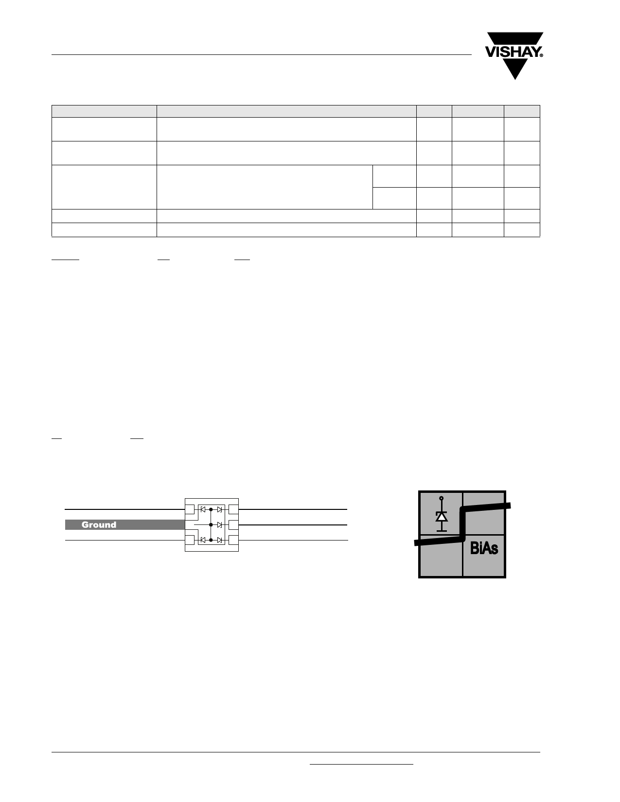
BiAs-Mode (5-line Bidirectional Asymmetrical protection mode)
With the GMF05C-HS3 up to 5 signal- or data-lines (L1 - L5) can be protected against voltage transients. With
pin 2 connected to ground and pin 1; 3 up tp pin 6 connected to a signal- or data-line which has to be protected.
As long as the voltage level on the data- or signal-line is between 0 V (ground level) and the specified Maximum
Reverse Working Voltage (VRWM) the protection diode between data line and ground offer a high isolation to
the ground line. The protection device behaves like an open switch.
As soon as any positive transient voltage signal exceeds the break through voltage level of the protection
diode, the diode becomes conductive and shorts the transient current to ground. Now the protection device
behaves like a closed switch. The Clamping Voltage (VC) is defined by the BReakthrough Voltage (VBR) level
plus the voltage drop at the series impedance (resistance and inductance) of the protection device.
Any negative transient signal will be clamped accordingly. The negative transient current is flowing in the
forward direction of the protection diode. The low Forward Voltage (VF) clamps the negative transient close to
the ground level.
Due to the different clamping levels in forward and reverse direction the GMF05C-HS3 clamping behaviour is
Bidirectional and Asymmetrical (BiAs).
L1
L2
20739
L5
1
5
L4
2
4
L3
3
3
www.vishay.com
2
For technical support, please contact: ESD-Protection@vishay.com
Document Number 85654
Rev. 1.8, 23-Sep-08
Share Link: 