HCF4521 データシートの表示(PDF) - STMicroelectronics
部品番号
コンポーネント説明
メーカー
HCF4521 Datasheet PDF : 12 Pages
| |||
HCF4521
FUNCTIONAL TEST SEQUENCE
Inputs
Outputs
Co mmen ts
RESET In2
Out2 VSS’ VDD’
Q18 thru
Q24
1
0
0
VDD GND
0
Counter is in three 8-stage sections in parallel mode.
Counter is reset. In2 and Out2 are connected togheter
0
1
1
VDD GND
0
First ”0” to ”1” transition on In2, Out2 node.
0
0
0
VDD GND
0
1
1
VDD GND
0
1
1
VDD GND
0
0
0
VDD GND
0
0
0
GND GND
0
255 ”0” to ”1” transitions are clocked into this In2, Out2
0
node.
1
The 255th ”0” to ”1” transition.
1
1
0
1
0
GND VDD
1
Counter converted back to 24-stages in series mode.
0
1
0
GND VDD
1
Out2 converts back to an output
0
0
1
GND VDD
0
Counter ripples from an all ”1” state to an all ”0” stage.
A test function (see fig.8) has been included forthe reduction oftest time required to exercise all 24 counter stages. This test function divides the counter
intothree 8-stage sections and 255 counts are loaded in each of the 8-stage sections in parallel. All flip-flopare now ata logic ”1”. The counter is now
returned to the normal 24-stages in series configuration. One more pulse is entered intoInput 2 (In2) which will cause the counter to ripple from an all ”1”
state to an all ”0” state.
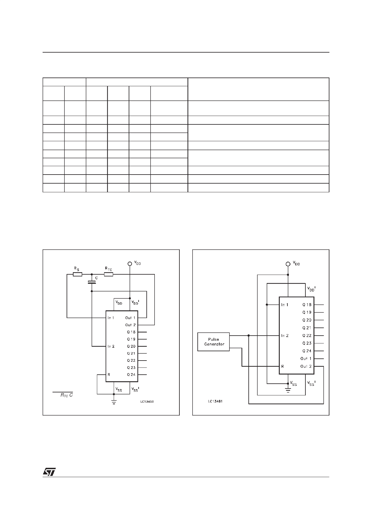
RC Oscillator Circuit
Functional Test Circuit
f
≅
2.3
1
RTC
C
RS ≥ 2 RTC
f in Hz, R in Ohms, C inFarads
7/12
Share Link: 