HDMP-1687 データシートの表示(PDF) - HP => Agilent Technologies
部品番号
コンポーネント説明
メーカー
HDMP-1687
HP => Agilent Technologies

HDMP-1687 Datasheet PDF : 16 Pages
| |||
Timing Characteristics for Gigabit Ethernet – Transmitter Section
T = 0°C Ambient to +85°C Case, VCC = 3.15 V to 3.45 V
Symbol
Parameter
Units Min. Typ. Max.
Ttxsetup
Tx Input Setup Time
ns
1.5
Ttxhold
t_txlat[1]
Tx Input Hold Time
Transmitter Latency
ns
0.5
ns
2.3
bits
2.8
Note:
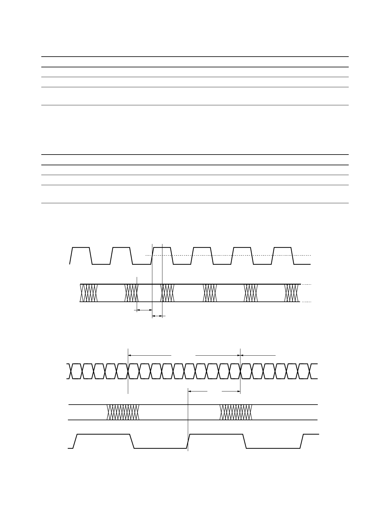
1. The transmitter latency, as shown in Figure 4, is defined as the time between the latching in of the parallel data word (as triggered by the rising edge of
the transmit byte clock, RFCT) and the transmission of the first serial bit of that parallel word (defined by the edge of the first bit transmitted).
Timing Characteristics for Fibre Channel – Transmitter Section
T = 0°C Ambient to +85°C Case, VCC = 3.15 V to 3.45 V
Symbol
Parameter
Units Min. Typ. Max.
Ttxsetup
Tx Input Setup Time
ns
2.0
Ttxhold
t_txlat[1]
Tx Input Hold Time
Transmitter Latency
ns
1.5
ns
3.8
bits
4.0
Note:
1. The transmitter latency, as shown in Figure 4, is defined as the time between the latching in of the parallel data word (as triggered by the rising edge of
the transmit byte clock, RFCT) and the transmission of the first serial bit of that parallel word (defined by the edge of the first bit transmitted).
RFCT
1.4 V
TX [0:3] [0:9]
DATA
DATA
DATA
ttxsetup
Figure 3. Transmitter section timing.
ttxhold
DATA
DATA
2.0 V
0.8 V
TX BYTE A
TX BYTE B
SO [0:3] ± S5 S6 S7 S8 S9 S0 S1 S2 S3 S4 S5 S6 S7 S8 S9 S0 S1 S2 S3 S4 S5 S6
t_txlat
TX [0:3] [0:9]
TX BYTE B
TX BYTE C
RFCT
Figure 4. Transmitter latency.
4
Share Link: