HT48RA0-3 データシートの表示(PDF) - Holtek Semiconductor
部品番号
コンポーネント説明
メーカー
HT48RA0-3 Datasheet PDF : 34 Pages
| |||
HT48RA0-3/HT48CA0-3
With the exception of the TO and PDF flags, the other
status register bits can be altered by instructions like
most other register. Any data written into the status regis-
ter will not change the TO or PDF flags. In addition it
should be noted that operations related to the status reg-
ister may give different results from those intended. The
TO and PDF flags can only be changed by the Watchdog
Timer overflow, device power-up, clearing the Watchdog
Timer and executing the HALT instruction.
The Z, OV, AC and C flags generally reflect the status of
the latest operations.
In addition, on executing a subroutine call, the status
register will not be automatically pushed onto the stack.
If the contents of the status are important and if the sub-
routine can corrupt the status register, precautions must
be taken to save it properly.
Oscillator Configuration
Only an external RC oscillator type is supported for the
HT48RA0-3/HT48CA0-3.
O SC1
12kW
R C O s c illa to r
System Oscillator
An external resistor between OSC1 and VSS in needed
whose resistance must be 12kW for a 4MHz frequency.
The RC oscillator provides ± 3% accuracy, the condi-
tions are:
· VDD= 2.0V ~ 3.6V
· Temperature = 0°C ~ +50°C
· fSYS= 4MHz
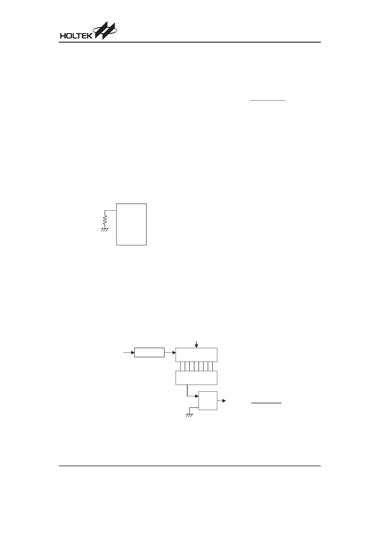
Watchdog Timer - WDT
The WDT clock source is implemented by the instruction
clock which is the system clock divided by 4. The clock
source is processed by a frequency divider and a
prescaler to provide various time out periods.
Clock Source
WDT time out period =
2n
Where n= 8~11 selected by a configuration option.
The WDT timer is designed to prevent a software mal-
function or sequence jumping to an unknown location
with unpredictable results. The Watchdog Timer can be
disabled by configuration option. If the Watchdog Timer
is disabled, all the executions related to the WDT result
in no operation and the WDT will lose its protection pur-
pose. In this situation the logic can only be restarted by
external logic.
A WDT overflow under normal operation will initialise a
²chip reset² and set the status bit ²TO². To clear the con-
tents of the WDT prescaler, two methods are adopted,
software instructions or a HALT instruction. There are two
types of software instructions. One type is the single in-
struction ²CLR WDT², the other type comprises two in-
structions, ²CLR WDT1² and ²CLR WDT2². Of these two
types of instructions, only one can be active depending on
the configuration option - ²CLR WDT times selection op-
tion². If the ²CLR WDT² is selected (i.e.. CLR WDT times
equal one), any execution of the CLR WDT instruction will
clear the WDT. In case ²CLR WDT1² and ²CLR WDT2² are
chosen (i.e.. CLR WDT times equal two), these two in-
structions must be executed to clear the WDT; otherwise,
the WDT may reset the chip due to a time-out.
C lo c k S o u r c e
( S y s te m C lo c k /4 )
F r e q u e n c y D iv id e r
3 - b it C o u n te r
C le a r W D T
P r e s c a lle r
( 8 - b it)
C o d e O p tio n
S e le c t
C ode
O p tio n
Watchdog Timer
W DT
T im e - o u t
C lo c k S o u r c e
2n
(n = 8 ~ 1 1 )
Rev.1.10
7
October 12, 2007
Share Link: 