46R01A3 データシートの表示(PDF) - Holtek Semiconductor
部品番号
コンポーネント説明
メーカー
46R01A3 Datasheet PDF : 58 Pages
| |||
HT46R01A
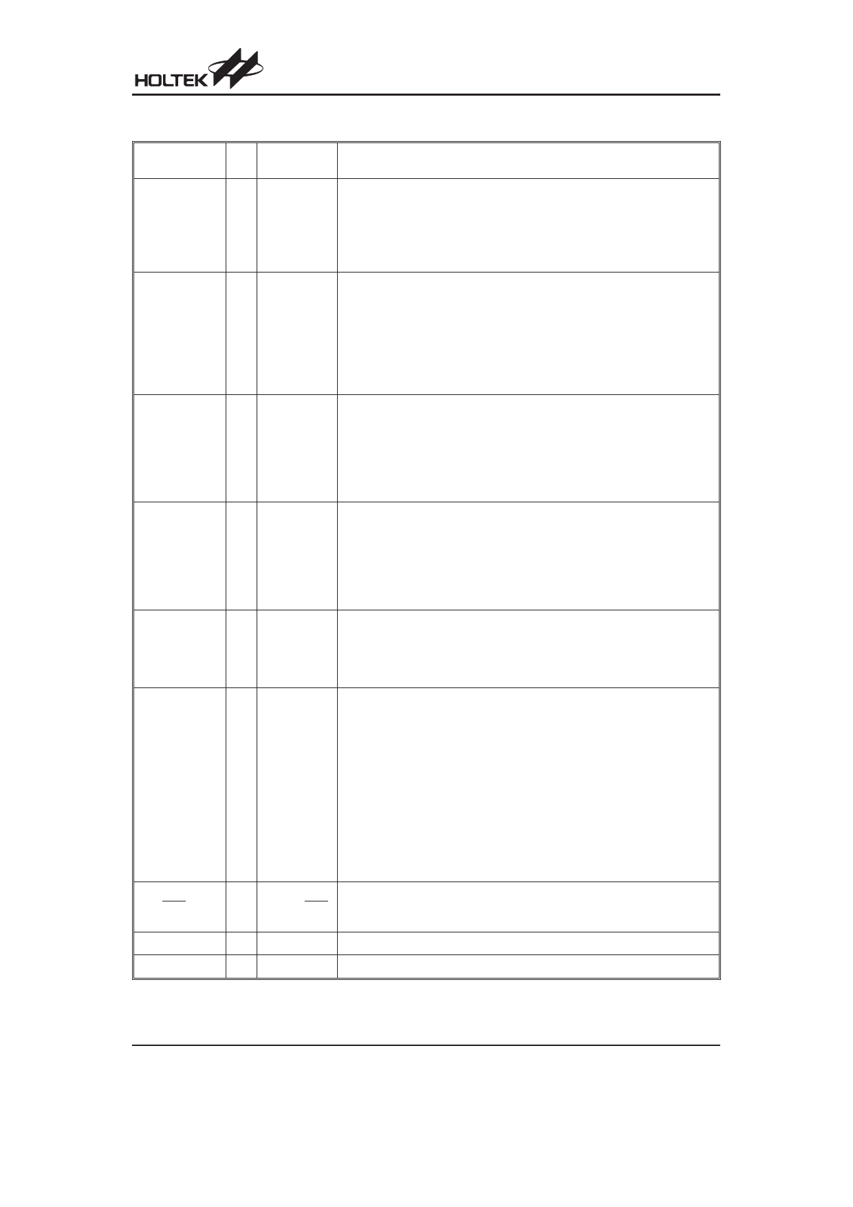
Pin Description
Pin Name
I/O
Configuration
Options
Description
PA0/AN0
Bidirectional single line I/O. The pin can be setup as a wake-up input using
the wake-up register. Software instructions determine if the pin is a CMOS
I/O
¾
output or a Schmitt Trigger input. A pull-high resistor can be connected using
the pull-high register. PA0 is pin-shared with the AN0 input pin. The A/D input
function is selected via software instructions. If selected as an A/D input, the
I/O function and pull-high resistor functions are disabled automatically.
PA1/PFD/AN1 I/O
Bidirectional single line I/O. The pin can be setup as a wake-up input using
the wake-up register. Software instructions determine if the pin is a CMOS
output or a Schmitt Trigger input. A pull-high resistor can be connected using
¾
the pull-high register. PA1 is pin-shared with the PFD output and the AN1 in-
put pin. The A/D input function is selected via software instructions. If selected
as an A/D input, the I/O function, PFD output and pull-high resistor functions
are disabled automatically. If the A/D function is not selected the PFD output
or I/O function selection is chosen via a bit in the CRTL0 register.
PA2/TMR0/AN2 I/O
Bidirectional single line I/O. The pin can be setup as a wake-up input using
the wake-up register. Software instructions determine if the pin is a CMOS
output or a Schmitt Trigger input. A pull-high resistor can be connected us-
¾
ing the pull-high register. PA2 is pin-shared with the TMR0 input and the
AN2 input pin. The A/D input function is selected via software instructions. If
selected as an A/D input, the I/O function, timer input and pull-high resistor
functions are disabled automatically.
PA3/INT/AN3 I/O
Bidirectional single line I/O. The pin can be setup as a wake-up input using
the wake-up register. Software instructions determine if the pin is a CMOS
output or a Schmitt Trigger input. A pull-high resistor can be connected us-
¾
ing the pull-high register. PA3 is pin-shared with the INT input and the AN3
input pin. The A/D input function is selected via software instructions. If se-
lected as an A/D input, the I/O function, external interrupt input and pull-high
resistor functions are disabled automatically.
Bidirectional single line I/O. The pin can be setup as a wake-up input using
the wake-up register. Software instructions determine if the pin is a CMOS
PA4/PWM
I/O
¾
output or a Schmitt Trigger input. A pull-high resistor can be connected us-
ing the pull-high register. PA4 is pin-shared with the PWM output pin. The
PWM output or I/O function selection is chosen via a bit in CTRL0 register.
PA6/OSC1
PA5/OSC2
Bidirectional 2-line I/O. The pins can be setup as wake-up inputs using the
wake-up register. Software instructions determine if the pins are CMOS out-
puts or Schmitt Trigger inputs. Pull-high resistors can be connected using
the pull-high register. Configuration options determine if the pins are to be
used as oscillator pins or I/O pins. Configuration options also determine
I/O
RC, Crystal,
RTC or I/O
which oscillator mode is selected. The four oscillator modes are:
1. Internal RC OSC: both pins configured as I/Os.
2. External crystal OSC: both pins configured as OSC1/OSC2.
3. Internal RC + RTC OSC: both pins configured as OSC2, OSC1.
4. External RC OSC+PA5: PA6 configured as OSC1 pin, PA5 configured
as I/O.
If the internal RC OSC is selected, the frequency will be fixed at either
4MHz, 8MHz or 12MHz, dependent upon which device is chosen.
PA7/RES
Active low Schmitt trigger reset input or PA7 input. A configuration option
I PA7 or RES determines which function is selected. PA7 has a wake-up function but does
not have a pull-high function.
VDD
¾
¾
Positive power supply
VSS
¾
¾
Negative power supply, ground
Note: Each pin on PA except PA7 can be selected to have a pull-high resistor.
Rev. 1.10
3
August 13, 2008
Share Link: 