HT9020 データシートの表示(PDF) - Holtek Semiconductor
部品番号
コンポーネント説明
メーカー
HT9020 Datasheet PDF : 12 Pages
| |||
HT9020
Pin Name
I/O
Internal
Connection
Description
CPTD mode: RBK=HIGH: The detected input signal is a
ringback tone.
RBK/KEY2 O CMOS OUT ABRC mode: Transmission gate input or output pin. Used to
trigger the row and column pin of the redial key when a dial
tone is received. It will output a 100ms pulse.
DIAL/KEY1 O
CMOS OUT
CPTD mode: DIAL=HIGH; The detected input signal is a
dial tone.
ABRC mode: Transmission gate input or output pin. Used to
trigger the row and column pin of the redial key when a dial
tone is received. It will output a 100ms pulse.
EN/KEY
CPTD mode: EN=VSS; Normal operation mode
EN=VDD; Device disabled. The oscillator stops and all output
I
CMOS IN
pins are pulled low or high impedance.
ABRC mode: The pin is schmitt trigger input structure.
Active low. Applying a negative going pulse to this pin can
toggle the auto-busy-redial function.
CLR
When CLR is low and BREAK is high, the tone decoder is
I
CMOS IN reset. This pin can be connected to the mute pin of the dialer
IC for tone elimination.
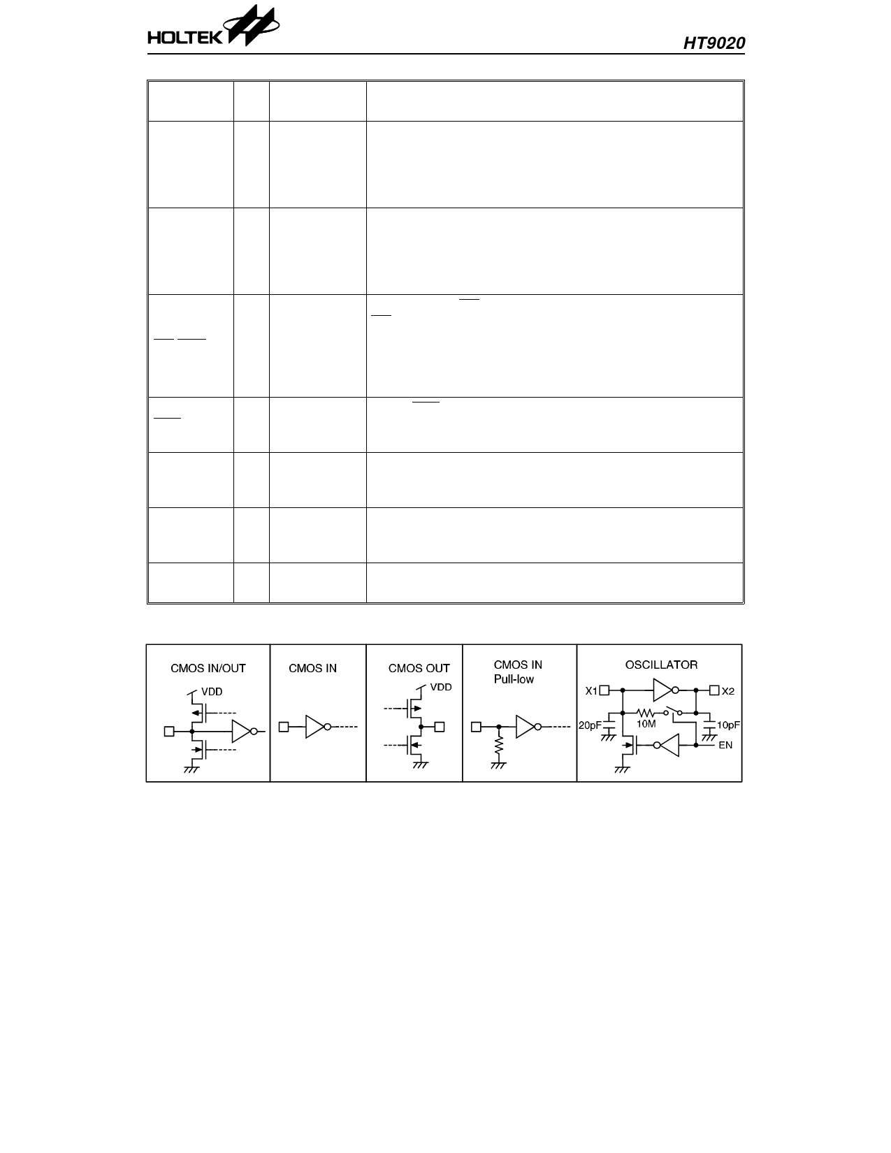
The system oscillator consists of an inverter, a bias resistor
X1
I OSCILLATOR and the necessary load capacitor on-chip. Connect a standard
32.768kHz crystal or ceramic resonator.
X1 and X2 terminals implement the oscillator function.
X2
O OSCILLATOR The oscillator is turned off in the standby mode, and is
actuated whenever a keyboard entry is detected.
TEST
I
CMOS IN
Pull-low
For testing only, active high
Approximate internal connection circuits
4
21st Aug ’98
Share Link: 