HV859(2006) データシートの表示(PDF) - Supertex Inc
部品番号
コンポーネント説明
メーカー
HV859 Datasheet PDF : 6 Pages
| |||
External Component Description
HV859
External Component
Diode
CS Capacitor
REL Resistor
Selection Guide Line
Fast reverse recovery diode, BAS21 diode or equivalent.
0.003µF to 0.1µF, 200V capacitor to GND is used to store the energy transferred from the inductor.
The EL lamp frequency is controlled via an external REL resistor connected between REL-OSC and VDD of the
device. The lamp frequency increases as REL decreases. As the EL lamp frequency increases, the amount
of current drawn from the battery will increase and the output voltage VCS will decrease. The color of the EL
lamp is dependent upon its frequency.
A 2MΩ resistor would provide lamp frequency of 205 to 275Hz. Decreasing the REL resistor by a factor of 2
will increase the lamp frequency by a factor of 2.
R Resistor
SW
Lx Inductor
The switching frequency of the converter is controlled via an external resistor, RSW between RSW-OSC and VDD
of the device. The switching frequency increases as RSW decreases. With a given inductor, as the switching
frequency increases, the amount of current drawn from the battery will decrease and the output voltage,
VCS, will also decrease.
The inductor LX is used to boost the low input voltage by inductive flyback. When the internal switch is
on, the inductor is being charged. When the internal switch is off, the charge stored in the inductor will be
transferred to the high voltage capacitor CS. The energy stored in the capacitor is connected to the internal
H-bridge, and therefore to the EL lamp. In general, smaller value inductors, which can handle more current,
are more suitable to drive larger size lamps. As the inductor value decreases, the switching frequency of
the inductor (controlled by RSW) should be increased to avoid saturation.
A 220µH Murata (LQH32CN221) inductor with 8.4Ω series DC resistance is typically recommended. For
inductors with the same inductance value, but with lower series DC resistance, lower RSW resistor value is
needed to prevent high current draw and inductor saturation.
Lamp
As the EL lamp size increases, more current will be drawn from the battery to maintain high voltage across
the EL lamp. The input power, (VIN x IIN), will also increase. If the input power is greater than the power
dissipation of the package, an external resistor in series with one side of the lamp is recommended to help
reduce the package power dissipation.
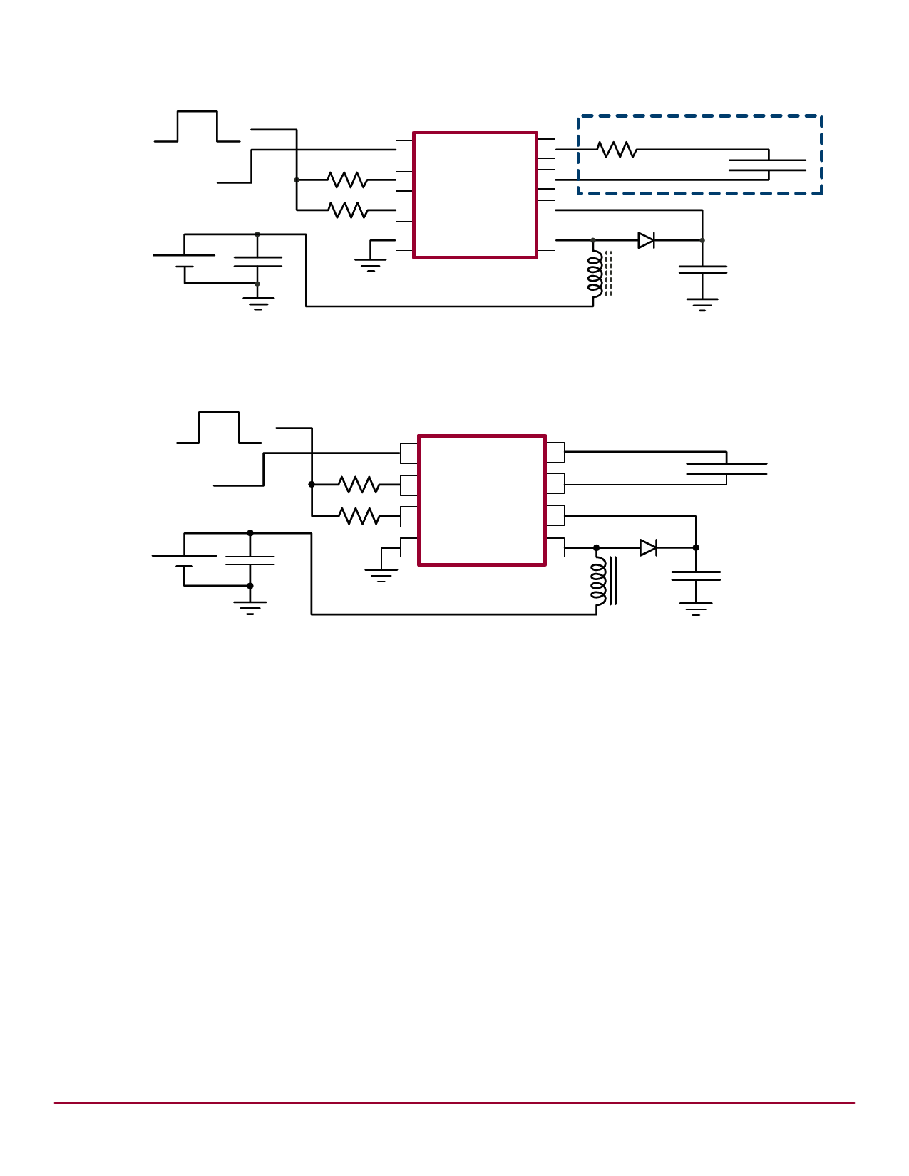
Split Supply Configuration
The HV859 can also be used for handheld devices operating from
a battery where a regulated voltage is available. This is shown in
Figure 2. The regulated voltage can be used to run the internal logic
of the HV859. The amount of current necessary to run the internal
logic is 150µA Max at a VDD of 3.0V. Therefore, the regulated voltage
could easily provide the current without being loaded down.
The HV859 can be easily enabled and disabled via a logic control
signal on the RSW and REL resistors as shown in Figure 2 below.
The control signal can be from a microprocessor. RSW and REL are
typically very high values. Therefore, only 10’s of microamperes
will be drawn from the logic signal when it is at a logic high (enable)
state. When the microprocessor signal is high the device is enabled,
and when the signal is low, it is disabled.
Figure 2: Split Supply and Enable/Disable Configuration
ON = VDD
Enable Signal
OFF = 0V
Regulated Voltage = VDD
+
VIN
-
RSW
REL
CIN
1 VDD
VA 8
2 RSW-osc
VB 7
3 REL-osc
CS 6
4 GND
LX 5
HV859MG/
HV859K7
D
LX
EL Lamp
CS
NR040306
4
Share Link: 