HWD489C データシートの表示(PDF) - Unspecified
部品番号
コンポーネント説明
メーカー
HWD489C Datasheet PDF : 20 Pages
| |||
Low-Power, Slew-Rate-Limited
RS-485/RS-422 Transceivers
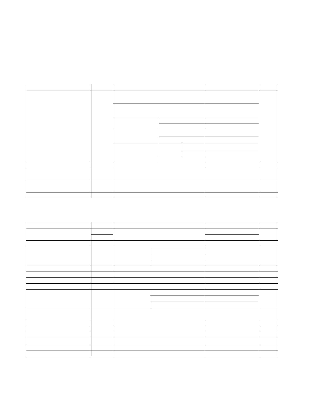
DC ELECTRICAL CHARACTERISTICS (continued)
(VCC = 5V ±5%, TA = TMIN to TMAX, unless otherwise noted.) (Notes 1, 2)
PARAMETER
SYMBOL
CONDITIONS
MIN TYP MAX UNITS
HWD488/HWD489,
DE, DI, RE = 0V or VCC
120
250
HWD490/HWD491,
DE, DI, RE = 0V or VCC
300
500
No-Load Supply Current
(Note 3)
HWD481/HWD485, DE = VCC
ICC
RE = 0V or VCC
DE = 0V
HWD1487,
RE = 0V or VCC
DE = VCC
DE = 0V
500
900
300
500
µA
300
500
230
400
Supply Current in Shutdown
ISHDN
HWD483/HWD487,
RE = 0V or VCC
DE = 5V
DE = 0V
HWD483
HWD487
HWD481/483/487, DE = 0V, RE = VCC
350
650
250
400
120
250
0.1
10
µA
Driver Short-Circuit Current,
VO = High
IOSD1 -7V ≤ VO ≤12V (Note 4)
35
250
mA
Driver Short-Circuit Current,
VO = Low
IOSD2 -7V ≤ VO ≤12V (Note 4)
35
250
mA
Receiver Short-Circuit Current
IOSR 0V ≤ VO ≤ VCC
7
95
mA
SWITCHING CHARACTERISTICS—HWD481/HWD485, HWD490/HWD491, HWD1487
(VCC = 5V ±5%, TA = TMIN to TMAX, unless otherwise noted.) (Notes 1, 2)
PARAMETER
SYMBOL
CONDITIONS
MIN TYP MAX
Driver Input to Output
tPLH
tPHL
Figures 6 and 8, RDIFF = 54Ω,
CL1 = CL2 = 100pF
10
30
60
10
30
60
Driver Output Skew to Output
tSKEW Figures 6 and 8, RDIFF = 54Ω, CL1 = CL2 = 100pF
5
10
Driver Rise or Fall Time
tR, tF
Figures 6 and 8, HWD481, HWD485, HWD1487 3
RDIFF = 54Ω,
HWD490C/E, HWD491C/E
5
CL1 = CL2 = 100pF HWD490M, HWD491M
3
15
40
15
25
15
40
Driver Enable to Output High
Driver Enable to Output Low
Driver Disable Time from Low
tZH Figures 7 and 9, CL = 100pF, S2 closed
tZL Figures 7 and 9, CL = 100pF, S1 closed
tLZ Figures 7 and 9, CL = 15pF, S1 closed
40
70
40
70
40
70
Driver Disable Time from High
Receiver Input to Output
tHZ Figures 7 and 9, CL = 15pF, S2 closed
Figures 6 and 10, HWD481, HWD485, HWD1487 20
tPLH, tPHL RDIFF = 54Ω,
HWD490C/E, HWD491C/E 20
CL1 = CL2 = 100pF HWD490M, HWD491M
20
40
70
90
200
90
150
90
200
| tPLH - tPHL | Differential
Receiver Skew
tSKD
Figures 6 and 10, RDIFF = 54Ω,
CL1 = CL2 = 100pF
13
Receiver Enable to Output Low
tZL Figures 5 and 11, CRL = 15pF, S1 closed
Receiver Enable to Output High tZH Figures 5 and 11, CRL = 15pF, S2 closed
Receiver Disable Time from Low tLZ Figures 5 and 11, CRL = 15pF, S1 closed
Receiver Disable Time from High
tHZ Figures 5 and 11, CRL = 15pF, S2 closed
20
50
20
50
20
50
20
50
Maximum Data Rate
Time to Shutdown
fMAX
tSHDN HWD481 (Note 5)
2.5
50
200 600
UNITS
ns
ns
ns
ns
ns
ns
ns
ns
ns
ns
ns
ns
ns
Mbps
ns
3
Share Link: 